3 4
5
1
Front
Left
Right
11
8
13
12
10
2
7
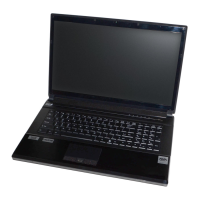
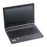
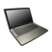
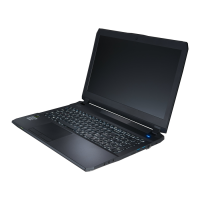
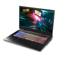
Figure 6 - Front, Left & Right Views (Model B)
1. LED Indicators
2. Security Lock Slot
3. Vent
4. DC-In Jack
5. HDMI-Out Port
6. Mini DisplayPorts
7. USB 3.1 Gen 2 Type-C Ports
8. USB 3.0 (USB 3.1 Gen 1) Type-A Ports
9. *Powered USB 3.0 (USB 3.1 Gen 1)
Type-A Port
*Toggle power to this port by using Fn +
Power Button (see Table 2 on
page 9).
10. Microphone-In Jack
11. 2-In-1 Audio Jack
(Headphone & S/
PDIF Out Combo
Jack)
12. Multi-in-1 Card
Reader
13. (Optional for
Design I) USIM
Card Reader (for 4G
USIM Cards)
14. RJ-45 LAN Jack
USIM Card Ejection
Simply press on the
USIM card to eject it,
however do not do
this while a connec-
tion is in progress.
If you do eject the card
while a 4G connection
is ongoing, you will
need to shut down the
system, reinsert the
USIM card, restart the
system and then rees-
tablish the 4G con-
nection.
If you wish to change
USIM cards then you
will also need to shut
down the system, re-
insert the USIM card,
restart the system and
then reestablish the
4G connection.
9
6
7
8
14
6
USIM Card
Orientation
Note that the USIM
card’s readable side
(with the gold-colored
contacts) should face
upwards as illustrated.
Overheating
To prevent your com-
puter from overheating
make sure nothing
blocks any vent while
the computer is in use.
 Loading...