Do you have a question about the Clevo W510TU and is the answer not in the manual?
Legal notices regarding publication revisions, liability, and trademarks used within the manual.
Manual's purpose, audience, and organization for service personnel.
Crucial safety precautions to reduce risk of fire, shock, and injury.
Suggestions to prevent damage and ensure proper operation of the notebook computer.
Requirements and precautions for safe use of the computer's power adapter and supply.
Guidelines and precautions for handling, charging, and storing notebook batteries.
Guidance on additional manuals and the initial setup process for the notebook.
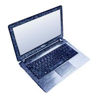
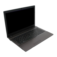
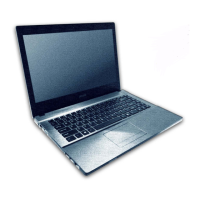
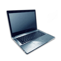
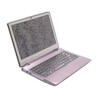
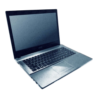
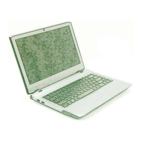
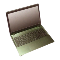
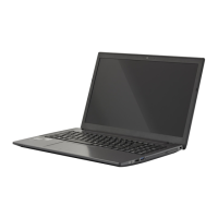
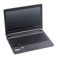
General introduction to the W510TU notebook computer and manual scope.
Detailed technical specifications of the W510TU notebook, including CPU, memory, and interface.
Identification of components on the top view of the notebook with the LCD panel open.
Identification of ports and indicators on the front and right side of the notebook.
Identification of ports and vents on the left side and rear of the notebook.
Identification of components and vents on the bottom view of the notebook.
Identification of key components on the top side of the notebook's mainboard.
Identification of key components on the bottom side of the notebook's mainboard.
Identification of external connectors on the top side of the notebook's mainboard.
Identification of external connectors on the bottom side of the notebook's mainboard.
Introduction to the disassembly process, procedures, and warning symbols used.
Recommended tools and types of internal computer connections for disassembly.
Crucial precautions to prevent injury/damage and guidelines for cleaning the computer.
Step-by-step guide for safely removing the notebook's battery.
Step-by-step guide for removing the notebook's keyboard assembly.
Step-by-step guide for removing the notebook's hard disk drive.
Step-by-step guide for removing and replacing the notebook's system memory modules.
Step-by-step guide for removing the notebook's wireless LAN module.
Step-by-step guide for removing the notebook's click board module.
Step-by-step guide for removing the notebook's MSATA storage module.
Step-by-step guide for removing the notebook's CCD (camera) module.
Table indicating where to find illustrations for specific part lists of the notebook.
Illustration and part numbers for the top case components (10W configuration).
Illustration and part numbers for the top case components (43W configuration).
Illustration and part numbers for the bottom case components (10W configuration).
Illustration and part numbers for the bottom case components (43W configuration).
Illustration and part numbers for the LCD panel and related components.
A high-level overview of the W510TU notebook's system architecture and component connections.
Schematic diagram for the System on Chip (SOC) memory interfaces.
Schematic diagram for the System on Chip (SOC) display interfaces.
Schematic diagram for the System on Chip (SOC) SATA and PCI Express interfaces.
Schematic diagram for the System on Chip (SOC) PMU and clocks.
Schematic diagram for the System on Chip (SOC) USB and touch panel interfaces.
Schematic diagram for the System on Chip (SOC) power delivery.
Schematic diagram for the System on Chip (SOC) power rails.
Schematic diagram for the System on Chip (SOC) VSS connections.
Schematic diagram for the DDR3 SO-DIMM memory slot and interface.
Schematic diagram for the PS8625 component, likely related to display or power.
Schematic diagrams for the LCD panel connector and CRT port.
Schematic diagram detailing the HDMI connector and its associated circuitry.
Schematic diagram for the ALC269 audio codec and related audio circuitry.
Schematic diagram for the AU6259-JGF USB hub controller.
Schematic diagrams for the HDD interface, touch panel, LEDs, and G-sensor.
Schematic diagrams for the USB 3.0 port and touch panel controller.
Schematic diagrams for the CPU fan, CCD, click button, and TV connections.
Schematic diagrams for the Mini Card slots supporting 3G, mSATA, and WLAN modules.
Schematic diagram for the Keyboard Controller (KBC) ITE IT8587E.
Schematic diagrams showing the system's various power rails and regulators.
Schematic diagrams detailing the VDD3 and VDD5 power supply circuits.
Schematic diagrams for 1.5VS, 1.8VA, and VTT_MEM power rails.
Schematic diagrams for 1.0VA and 1.05VS power rails.
Schematic diagrams for 0.85VS and 1.8VS power rails.
Schematic diagram for the AC adapter input and charging circuitry.
Schematic diagram for the AC power input connector.
Schematic diagram for the notebook's audio board and USB ports.
Schematic diagram for the RTL8402 LAN controller and card reader interface.
Schematic diagram for the power switch, LEDs, and related circuitry.
Schematic diagram for the click board, likely related to touchpad or buttons.
Schematic diagram for level shifting circuits, possibly for HDMI or SMBus.
Schematic diagram for additional level shifting circuits, possibly for system control signals.
A block diagram illustrating the power distribution and voltage rails within the notebook.
Timing diagram showing the sequence of power-on signals and states.
Step-by-step guide on how to download, prepare, and update the notebook's BIOS.
| Weight | 2.5 kg |
|---|---|
| Memory Speed | 1600MHz |
| RAM | Up to 16GB DDR3L |
| Storage | Supports 2.5" 9.5mm HDD/SSD, mSATA SSD |
| Display | 15.6" Full HD (1920x1080) |
| Optical Drive | DVD-RW or Blu-Ray Combo (optional) |
| Audio | High Definition Audio |
| LAN | 10/100/1000Mbps |
| WLAN | 802.11b/g |
| Webcam | 2.0MP |
| Card Reader | 4-in-1 (SD, MMC, MS, MS Pro) |
| Ports | HDMI, VGA, RJ-45 |
| Battery | 6-Cell Battery |