EasyManua.ls Logo

Clifford Matrix +1 User Manual

Clifford Matrix +1
40 pages
To Next Page IconTo Next Page
Page #1 background imageLoading...
Page #1 background image
NOTE: This product is intended for installation by a professional
installer only! Any attempt to install this product by any person other
than a trained professional may result in severe damage to a vehicle’s
electrical system and components.
Matrix +1
Installation Guide
©2008 Directed Electronics, Vista, Ca.
N3105X- 2008-12
Question and Answer IconNeed help?

Do you have a question about the Clifford Matrix +1 and is the answer not in the manual?

Clifford Matrix +1 Specifications

General IconGeneral
BrandClifford
ModelMatrix +1
CategoryCar Alarm
LanguageEnglish

Summary

Primary Harness (H1) Wire Connection Guide

Primary Harness Wiring Diagram

Diagram showing the connections and wire functions for the primary harness.

Primary Harness Wiring Instructions

Detailed instructions for connecting each wire of the primary harness.

H1/2 WHITE (+/-) Light Flash Output

H1/3 WHITE/BLUE 200 mA (-) Channel 3 Output

H1/4 BLACK/WHITE (-) 200 mA Domelight Supervision Output

H1/5 GREEN (-) Door Trigger Input

H1/6 BLUE (-) Instant Trigger Input

H1/7 VIOLET (+) Door Trigger Input

H1/8 BLACK (-) Chassis Ground Connection

H1/9 YELLOW (+) Ignition Input

H1/10 BROWN (+) Siren Output

H1/11 RED (+)12V Constant Power Input

H1/12 RED/WHITE 200 mA (-) Channel 2 Output

Door Lock Harness (H2), 3-PIN Connector

Plug-In LED and Valet/Program Switch

Programmer Interface, 3-Pin BLACK Plug

Mounting the Control Center

On-Board Dual-Stage Shock Sensor

Optional Sensor Harness, 4-pin Connector

Programming Jumper

Bypassing Sensor Inputs

System Features Learn Routine

System Features Menus

Menu #1 - Basic Features

Lists and describes the basic system features and their default settings.

Menu #2 - Advanced Features

Feature Descriptions

Provides detailed explanations for system features, noting Bitwriter-specific settings.

Transmitter/Receiver Learn Routine

Transmitter Configurations

Standard Configuration

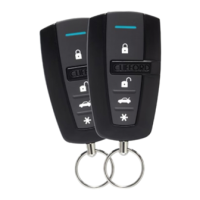
Details the functions assigned to buttons in the standard transmitter configuration.

Three-button Configuration

Describes the optional three-button transmitter configuration and its limitations.

Diagnostics

Arm/Disarm Diagnostics

Explains how siren chirps indicate the system's arming and disarming status.

System Status Chirps

A table detailing the meaning of different siren chirp counts for system status.

Table of Zones

Long Term Event History

Multi-Level Security Arming

Optional Vehicle Recovery System (VRS)

False Alarm Control Technology (FACT IITM)

Rapid Resume Logic

Troubleshooting

Starter Kill Issues

Addresses problems related to the starter kill function not working correctly.

Shock Sensor Alarm Issues

Helps diagnose why the shock sensor might not be triggering the alarm.

Progressive Door Input Behavior

Explains the expected chirping behavior for the progressive door trigger.

Door Trigger Logic

Discusses scenarios where closing triggers the system but opening does not.

Passive Arming Issues

Progressive Trigger and Alarm Mismatch

Valet Button Functionality

Status LED Issues

Related product manuals