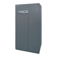
Do you have a question about the CLIMAVENETA i-ACCURATE Series i-AX and is the answer not in the manual?
| Brand | CLIMAVENETA |
|---|---|
| Model | i-ACCURATE Series i-AX |
| Category | Air Conditioner |
| Language | English |
Overview of the i-ACCURATE series of precision air-conditioners.
Lists the available models for direct expansion units.
Specifies air flow options for different models.
Details capacity options for the units.
Outlines the version types available for the units.
Provides a general description of the ductable precision air-conditioners.
Describes the construction and materials of the unit's frame and casing.
Details the types of compressors used, including their features.
Explains the function and operation of the immersed electrode humidifier.
Describes the microprocessor control system for direct expansion models.
Explains the different versions: BASIC, MOD, MOD.A, MOD.B, LT.
Details the water-cooled condenser for the i-AF units.
Explains the air-cooled version of the Dual Fluid unit.
Explains the different configurations for OVER units based on air intake/outlet.
Presents technical data tables for the i-AX unit.
Details specifications for the plate condenser used in i-AW units.
Lists the connection types and sizes for i-AF units.
Provides technical data for chilled water capacity of i-AD units.
Presents technical data for chilled water capacity of i-AT units.
Details performance data for the hot water re-heating system.
Shows performance data for hot gas reheating coils.
Explains how to access main components via front panels.
Describes the standard packaging of the units.
Lists the net weights of the different models and receiving instructions.
Provides dimensions for OVER units, Frame 2.
Provides dimensions for OVER units, Frame 4.
Provides dimensions for OVER units, Frame 5.
Provides dimensions for OVER units, Frame 6.
Provides dimensions for UNDER units, Frame 2.
Provides dimensions for UNDER units, Frame 3.
Provides dimensions for UNDER units, Frame 5.
Provides dimensions for UNDER units, Frame 6.
Details the optional support frame for unit installation.
Explains the necessary space for unit access and maintenance.
Specifies the environmental operating ranges for the units.
Details the optional base moulding for cable and pipe routing.
Describes intake plenums for UNDER units.
Details intake plenums for OVER units.
Explains the function of the motor-driven damper accessory.
Describes the optional front outlet plenum for OVER units.
Details the optional front outlet moulding for UNDER units.
Describes the soundproof plenum to be installed on the top of the unit.
Explains the direct free cooling plenum accessory for UNDER units.
Details the direct free cooling base accessory for OVER units.
Lists the components included in the free cooling connection kit.
Shows pressure drop charts for optional air filters.
Describes the optional fresh air kit and its installation.
Shows water connection positions and diameters for OVER units (12-18).
Details water connection positions for UNDER units (size 20-29).
Details water connection positions for OVER units (size 50).
Details water connection positions for OVER units (size 70).
Details water connection positions for UNDER units (size 70).
Details water connection positions for UNDER units (size 90).
Shows water connection positions for OVER units (size 130).
Provides recommendations for water connections to avoid vibrations and ensure ease of service.
Explains how to connect water-cooled units to the brazed plate condenser.
Details correction factors for using ethylene glycol mixtures.
Shows pressure drop charts for stainless steel pipes at 10°C.
Provides an example of how to select pipe sizes based on pressure drop.
Shows pressure drop charts for stainless steel pipes at 50°C.
Displays water flow rates for pressure drop calculations at 80°C.
Provides important notes for installing air condensers, including oil traps and non-return valves.
Lists recommended pipe diameters for refrigerant connections.
Details oil separator selection based on power cooling capacity.
Lists indoor coil volumes and refrigerant charges for various models.
Lists condenser coil volumes and refrigerant charges.
Provides refrigerant gas content per linear meter for different pipe diameters.
Explains how to fill the condensate drain trap during installation.
Details how to access the electrical panel and cable entry points.
Lists recommended minimum cross-sections for power cables.
Lists electrical specifications and cable cross-sections.
Presents data on compressor power consumption for different models.
Provides data on fan power consumption for different models.
Lists power consumption data for electric heaters.
Details power consumption data for the humidifier.
Explains parameter setting for condensation phase control of BRE-BDC.
Details the procedure for vacuuming and charging the refrigerant circuit.
Outlines the step-by-step procedure for unit commissioning.
Discusses operation and control for water-cooled units.
Lists the standard instruments and sensors fitted to the unit.
Lists additional sensors available on some unit versions.
Explains the calibration of control and safety devices.
Details the calibration procedure for the pressure control valve.
Steps to calibrate the air flow sensor's pressure switch.
Procedure for calibrating the dirty filter sensor.
Explains the electrical connection for the temperature and humidity probe.
Describes the operation of the servomotors and water valves.
Explains the function of the actuator based on control signals and manual override.
Information on actuator maintenance and repair procedures.
Explains the actuator's function with control signals.
Details the auto-calibration process for actuators.
Step-by-step calibration procedure for the SQX62 actuator.
Describes normal operation and LED indications for the actuator.
Indicates the operating status of the SQX62 actuator via LEDs.
Provides close-off values for 2-way valves.
Details the components of the electric heating system.
Lists the components of the immersed electrode humidifier.
Explains the steam cylinder and its cleaning process.
Details the periodic inspection of humidifier supply and drain assemblies.
Specifies limit values for humidifier feed water conductivity.
Warns about the hot water exiting the steam cylinder and drain hose installation.
Describes the standard condensate drain pump for low water temperatures.
Provides maintenance guidelines for the condensate pump.
Highlights important maintenance and testing for the high water temperature pump.
Explains how motorised changeover switches manage power supply switching.
Instructions for cleaning the air filters.
Guidance on checking water-cooled condensers for fouling.
Provides solutions for faults related to the air-conditioner not starting.
Addresses issues when room temperature is too high due to controller settings.
Troubleshooting steps when room temperature is too low.
Solutions for high ambient humidity due to incorrect controller settings.
Troubleshooting steps when ambient humidity is too low.
Troubleshooting steps when fans are not powered or airflow is restricted.
Explains why the heater safety thermostat might activate due to low airflow.
Addresses high discharge pressure caused by air/gas in the refrigerant circuit.
Troubleshoots low discharge pressure due to malfunctioning control systems.
Addresses high suction pressure caused by excessive thermal load.







 Loading...