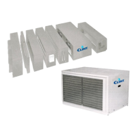
Luftintag och tilluftsutlopp i "kanalbara" versioner: kanalflänsanslutningar
Air intake and supply outlets of “ductable” versions:
duct flange connections
Fläns – Flange
(min. 15mm)
Fläns – Flange
(min. 15mm)
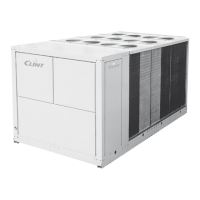
13 Installation: HYDRAULISK ANSLUTNING 13 installation: WATER SUPPLY CONNECTIONS
Vattenanslutningar ansluts med mekaniska
kopplingar
•
I enlighet med de europeiska direktiven och
förordningarna om ECODESIGN måste rören vara av
lämplig storlek (stora sektioner etc.) för att
säkerställa låga tryckfall (tryckfall
är alltid en källa
energiförlust
, med åtföljande försämring av
enhetens prestanda och energieffektivitet och av
systemet i allmänhet).
•
VVS-anslutningar måste göras med rör med en
diameter som
är större (eller åtminstone lika, aldrig
sämre
) än enhetens VVS-anslutningar!
• Tillhandahåll avstängningsventiler (av lämplig
storlek, MIN 1/2") för att isolera batteriet från resten
av kretsen vid extraordinärt underhåll. Anslut
inloppet med en kulventil och utloppet med en
balanseringsventil eller låssköld (eller installera 2
kulventiler).
•
Tillhandahåll en avluftningsventil upptill och en
avtappningsventil i
botten.
•
Obligatoriskt: Isolera vattenledningar och ventiler
ordentligt för att förhindra dropp under kylning.
•
Värmeväxlarslingorna för vatten är testade vid ett tryck
på 30 bar och är därför lämpliga för drift
upp till ett
maximalt tryck på 15 bar.
Observera att de främsta orsakerna till batterifel är:
•
Brott/sprickor på svetsar eller rör som kan hänföras till en onormal mekanisk påverkan (t.ex. stötar
och/eller
forcering under hantering, transport, hantering och särskilt under installation), i synnerhet
tvingande under montering på grund av för kraftig åtdragning utan användning av momentnyckel
.
•
Överdriven termisk expansion av tillförselrören (på grund av den olika varma/kalla
vattentemperaturen), expansioner som under vissa omständigheter (t.ex. linjära rör som är för
långa) kan bli uppenbara och därför farliga om de släpps ut på enhetens grenrör.
•
Viktavlastning, vibrationsöverföring eller deformation av rörledningar
på enhetens grenrör.
OBLIGATORISKT, därför, enligt systemets särdrag (som ska utvärderas från fall till fall),
användningen av konsoler, expansionsfogar, antivibrationer och anta alla de systemåtgärder
som är utformade för att inte tömma vikten, deformationerna och vibrationerna hos
matningsrören på enhetens grenrör.
Risk för frysning: Installera frostskyddsanordningarna om enheten, avlopps- eller VVS-
anslutningarna kan utsättas för temperaturer nära 0 °C (t.ex.: skydda rören med värmekablar
placerade under isoleringen, isolera rören etc.). Om enheten är installerad i särskilt kalla rum, töm
ur vattentanken under långa viloperioder.
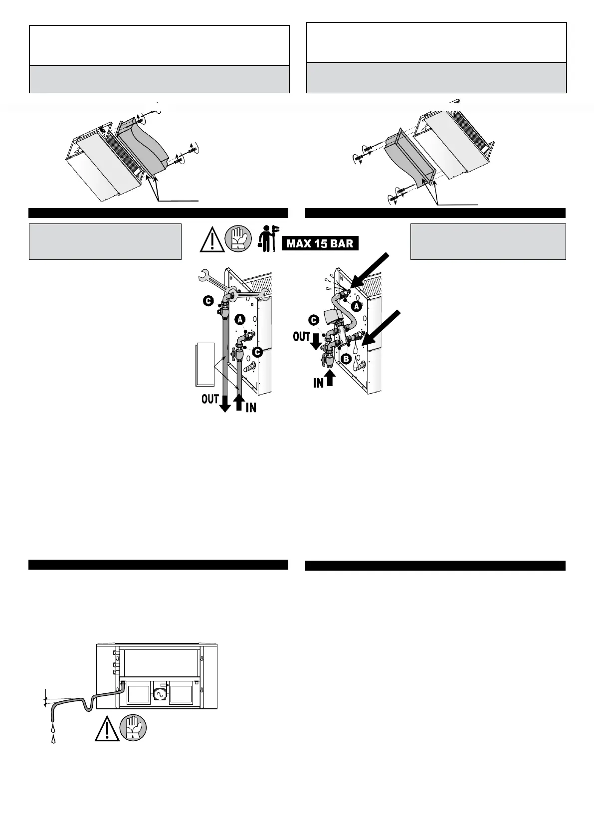
14 Installation: KONDENSATAVLOPP
För versioner som används vid kyldrift med kondensatgenerering:
•
Obligatoriskt: isolera kondensrören på lämpligt sätt för att förhindra dropp i kyldrift.
•
Kondensatavlopp måste vara av lämplig storlek och rören placerade på
ett sådant sätt att en
lämplig lutning längs vägen bibehålls (minst 3 %) och får inte ha
stigande sektioner eller
flaskhalsar för att tillåta regelbundet utflöde.
•
Obligatoriskt: installera ett vattenlås på kondensatavloppsröret.
•
Kondensatavloppet måste anslutas till avloppsnät.
•
Använd inte vit- eller svartvattenavlopp (avloppssystem) för att undvika eventuellt sug av dålig
lukt
mot rummen i händelse av avdunstning av vattnet i vattenlåset.
Concerning the water coil versions: Make hydraulic
connections
•
In compliance with the European directives and regu-
lations referring to ECODESIGN, the ducts must be
properly sized (large sections, few and slight changes
of direction, etc.) in order to guarantee low pressure
drops (pressure drops are always source of waste and
energy dissipation, with consequent loss of the perfor-
mances and of the energy efficiency of the unit and of
the installation in general).
•
The hydraulic connections have to be realized with pi-
pes with higher diameter (or minimum limit equal, but
never smaller) of the unit’s hydraulic connections !
•
Install shut-off valves (of suitable dimensions, MIN
1/2”)
to isolate the coil from the rest of the circuit in the
event of special maintenance. Connect the inlet water
with a shut off valve and the outlet with a balancing valve
(or installed 2 shut off valves).
•
Fit a breather valve above and a discharge valve below.
•
Compulsory: appropriately insulate water valves and
pipes to prevent dripping in cooling mode.
•
The water coils are tested at a pressure of 30 Bar and
therefore they can operate at a maximum pressure of
15 Bar.
Please note that the main causes of coil breakage are:
•
Breakage/cracking of welds or pipes due to an abnormal mechanical shock (e.g. impact and/or for-
cing during handling, transport and especially during installation), in particular forcing during assembly
for tightening too vigorously without the use of anti-torsion systems such as key and counter-keys.
•
Excessive thermal expansion of the return water pipes (different temperature between hot/cold water),
expansions that in certain circumstances (e.g. too long pipes) may become evident and therefore
dangerous in case they of discharge on the unit’s manifolds.
•
Discharge of the weights, transmission of vibrations or deformations of the pipes of the supply system on
the manifolds of the unit.
MANDATORY, therefore, according to the peculiarities of the installation (to be evaluated on
a case-by-case basis), the use of brackets, expansion joints, anti-vibration systems and to
adopt all required precautions to avoid the discharge of the weight, deformations and vibra-
tions of the return pipes on the manifolds of the unit.
Risk of freezing: Install the antifreeze devices if the unit, drain or plumbing connections can be subject
to temperatures close to 0 °C (ex.: safeguard the pipes with heating cables placed under the insulation,
insulate the pipes, etc.). If the unit is installed in particularly cold rooms, fill out the water tank during
long rest periods.
14 installation: DRAIN PIPE
Concerning
the
versions
used
in
cooling
with
condensate
generation:
•
Compulsory:
appropriatly
insulate
condensate
pipes
to
prevent
dripping
in
cooling
mode.
•
Install an appropriate size condensate drainage system and place it to favour the discharge (min 3%
slope) and must not have rising parts or stranglings in order to allow a regular downflow.
•
Compulsory: install a siphon in condensate drainage system.
•
The drain pipe will be connected to an unloading rain network.
•
Do not use white or black water (sewage system) to prevent unpleasant odour return into the room in
case of evaporation of the water contained in the siphon.
Caution: for connecting the coil to the pipes always
use anti-torsion systems (eg. a key and counter-key)
and tighten with a proper tightening torque, to avoid
to break the coil.
Försiktighet: för att ansluta batteriet till rören, använd
alltid anti-torsionssystem (t.ex. en nyckel och
motnyckel) och dra åt med ett korrekt
åtdragningsmoment, för att undvika att batteriet går
In compliance with the European directives and regulations referring to ECODESIGN, the
ducts
must be
pro-
perly sized (large sections, few and slight changes of direction, etc.) in order to guarantee low pressure drops
(pressure
drops
are
always
source
of
waste
and
energy
dissipation,
with
consequent
loss
of
the
performances
and of the energy efficiency of the unit and of the installation in general).
The air intake and air supply ducts must always be realized with a larger section (or same,
but never smaller) than the air outlet of the unit, otherwise the @ESP performance will be
lost (due to the air pressure drops).
I enlighet med de europeiska direktiven och förordningarna om ECODESIGN måste kanalerna vara
storlek (stora sektioner, få och små riktningsändringar etc.) för att säkerställa låga
tryckfall (tryckfall är alltid en
källa till energiförlust, med åtföljande
försämring av enhetens och systemets prestanda och energieffektivitet
i allmänhet).
Luftintags- och lufttillförselkanalerna måste alltid vara större (eller samma, men aldrig mindre) än
enhetens luftutlopp, annars kommer @ESP prestandan att gå förlorad (på grund av lufttrycksfall
)
 Loading...