UNIT MANUFACTURED ACCORDING WITH 2006/95/CE STANDARD (EX 73/23/CEE)
ENHET BYGGD I ENLIGHET MED DIREKTIVET 2006/95/CE (EX 73/23/CEE)
Dr
ä
neringsavloppet skall ha ett vattenl
å
s av l
ä
mplig storlek f
ö
r att:
•
Låta kondensatet rinna av fritt.
•
Förhindra att oönskad luft tränger in.
•
Förhindra oavsiktligt läckage av luft från den trycksatta kretsen.
•
Förhindra infiltration av lukt eller insekter.
OBS: Sifonen ska ha en plugg för att underlätta rengöring av den nedre delen och vara lätt att ta isär.
Följ anvisningarna nedan för att designa sifonen
.
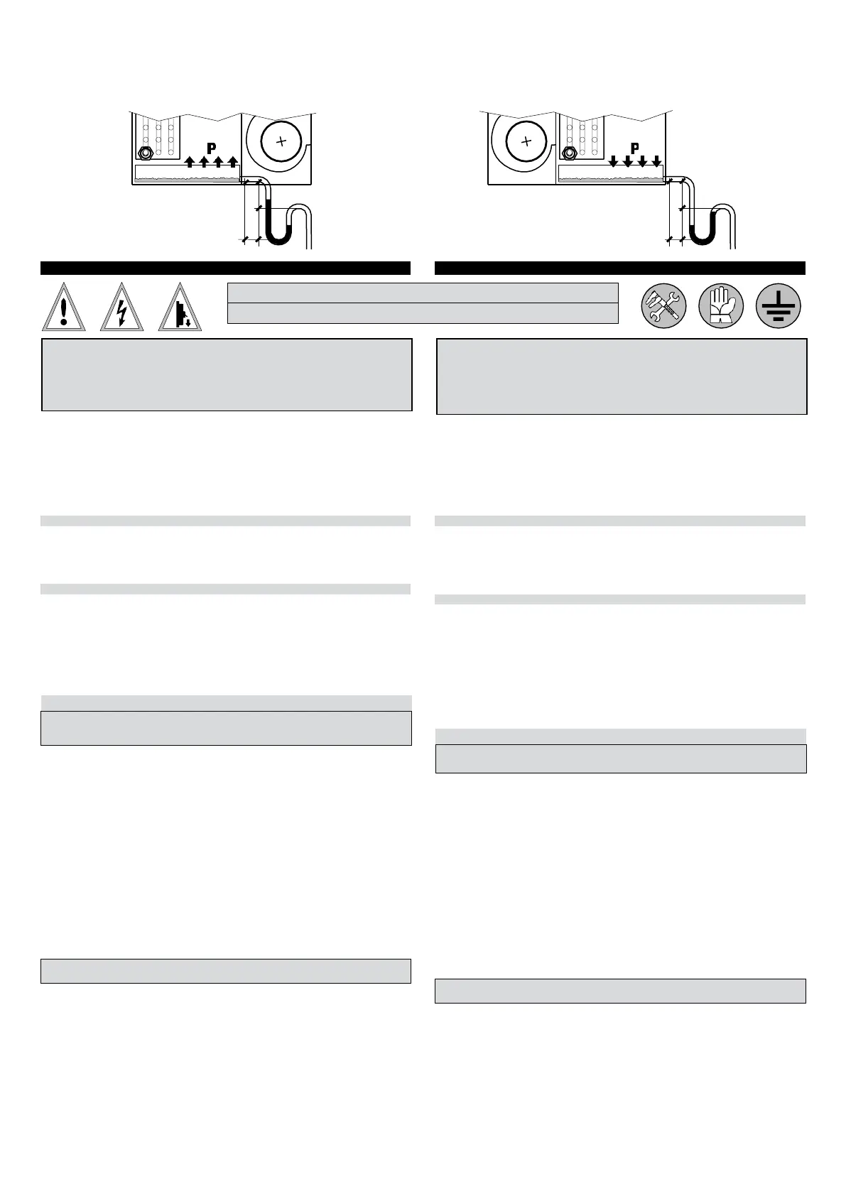
The drainage system should feature an adequately sized siphon to:
•
Ensure
free
condensate
drainage.
•
Prevent the inadvertent entry of air into the circuit under negative pressure.
•
Prevent
the
inadvertent
leakage
of
air
from
the
pressurised
circuit.
•
Prevent
the
entry
of
unpleasant
odours
and
insects.
NOTE: The
siphon
should
have
a
plug
to
facilitate
cleaning
of
the
lower
section, and
be
easy
to
disassemble.
Follow
the
indications
below
for
design
the
siphon.
Undertryck
Negative pressure
•
H1 (mm) = P + 30 mm
•
H2 (mm) = H1 = P + 30 mm
•
H3 (mm) = H1 + H2 = 2P + 60m
Där P är det tryck som uttrycks
i mm vattenpelare
(1 mm AC = 9,81 Pa)
Where P is pressure expressed
in mm of water gauge
(1
mm
c.a.
=
9.81
Pa)
15 Installation: ELEKTRISK ANSLUTNING 15 installation: ELECTRICAL CONNECTIONS
•
Följ EEG:s säkerhetsföreskrifter och gällande standarder/lagar i installationslandet.
•
Kontrollera att det elektriska nätverkets egenskaper överensstämmer med enhetens
märkskyltsdata.
•
Nätaggregat och tillbehör (motor, värmeelement, fjärrkontroller, reglering,
etc.): Kontrollera
att nätspänningen ligger inom de fastställda gränserna (se
driftsgränser).
•
Användning av enheten med spänning utanför ovanstående gränser upphäver garantin.
•
Se till att det elektriska systemet inte bara kan leverera den driftström som krävs
av enheten
utan även den ström som krävs för att driva andra apparater och enheter som redan
används.
KONTROLLERA JORDANSLUTNINGEN
•
Enhetens elektriska säkerhet uppnås endast när den är korrekt ansluten till ett effektivt
jordningssystem, utfört i enlighet med gällande säkerhetsstandarder.
•
Vid anslutning ska jordledningen vara längre än de strömförande. Det kommer att vara den
sista kabeln som slits sönder om strömkabeln dras av misstag och därför kommer
en god
jordkontinuitet att förbli säkerställd.
ANSLUTNINGSKABLARNAS EGENSKAPER
•
Anslut enheten och alla dess tillbehör med kablar med lämpligt diameter för den berörda
strömmen och i enlighet med lokala föreskrifter. Deras storlek måste dock vara
tillräcklig för att
uppnå ett spänningsfall under uppstart på mindre än 3 % av
den nominella spänningen.
•
Använd kablar av typen H05V-K eller N07V-K med 300/500V isolering inbäddad i röret eller ledningen.
•
För enheter med växelriktare/drivrutin eller annan frekvensvarierande enhet, använd skärmad kabel.
•
Alla kablar måste vara infällda i kanal eller ledningen tills de är inuti
enhetens kopplingsplint.
•
Kablarna vid rörets eller ledningens utlopp måste placeras på ett sådant sätt att de inte utsätts
för spänning eller vridning och under alla omständigheter skyddas från yttre påverkan. Tvinnade
kablar kan endast användas med kabelskor. Se till att trådtrådarna är väl insatta.
ELEKTRISK ANSLUTNING OCH DIFFERENTIELL MAGNETOTERMISK ALLPOLIG STRÖMBRYTARE
ALLA KOPPLINGSSCHEMAN ÄR FÖREMÅL FÖR UPPDATERINGAR: VI FÖRESLÅR ATT DU
HÄNVISAR TILL KOPPLINGSSCHEMAT SOM INGÅR I VARJE ENHET.
•
Det är obligatoriskt att förlita sig på en konstruktör och använda certifierade komponenter av högsta kvalitet, med
egenskaper som är lämpliga för
det specifika systemet i vilket de är installerade och för egenskaperna hos de
komponenter som är monterade på enheten/tillbehöret som
ska drivas.
•
Gör den elektriska anslutningen enligt enhetens kopplingsschema.
•
Det är inte tillåtet att använda adaptrar, grenuttag och/eller förlängningssladdar för enhetens allmänna
strömförsörjning.
•
För att skydda enheten mot kortslutning måste enheten anslutas till strömförsörjningsledningen
med hjälp av en
lämplig jordfelsbrytare med en minsta kontaktöppning på 3 mm. Denna strömbrytare måste garantera
tillräckligt överbelastningsskydd (termisk del) + kortslutningsskydd (magnetisk del) + skydd mot elektriskt
läckage, fel eller elstöt till jord (
differentiell del). För val av den lämpligaste strömbrytaren, se strömförbrukning
på enhetens etikett.
•
Kom ihåg: en omnipolär omkopplare definieras som en med möjlighet att öppna både på fasen och på nollan.
Det
betyder att båda kontakterna är öppna när den öppnas.
•
Den allpoliga strömbrytaren eller valfri kontakt (anslutning med kabel och stickpropp) måste placeras
på tillgängliga platser.
•
Det rekommenderas att alltid installera en extra säkringsfrånskiljare uppströms som, förutom att erbjuda
tillräckligt
extra skydd, gör det möjligt att, tack vare borttagningen av säkringarna, helt koppla bort ledningen med ett
kontaktavstånd
>3 mm.
•
Det är installatörens skyldighet att installera strömförsörjningen så nära frånkopplingsenheten som möjligt !!
EFFEKTFÖRBRUKNING
:
Se strömförbrukningsvärdena som visas på enhetens märketikett.
För enheter med asynkronmotor med flera hastigheter (AC) (t.ex.
min/med/max):
VARJE KONTROLLPANEL KAN ENDAST STYRA EN ENHET !!
OBS: För att styra mer än en enhet (eller en enhet med 2 motorer) rekommenderas att hålla strömförsörjningen till
de
olika motorerna SEPARATA OCH OBEROENDE. För att göra detta rekommenderas det att installera 3 reläer (ett för
varje
hastighet) med oberoende kontakter (en kontakt för varje motor som ska styras) eller att installera INTERFACE BOARD
(tillbehör
): på detta sätt stör eller påverkar inte någon anomali som skulle ingripa i en motor de andra !!
Tillbehör: Fjärrkontroller:
Kontrollpanelens placering måste väljas så att den maximala och lägsta
omgivningstemperaturgränsen är 0÷45 °C, < 85 % RH. Kontrollpanelen får inte monteras på en metallvägg om den
inte är permanent ansluten till jorduttaget.
Tillbehör: Lägsta vattentemperaturtermostat:
Termostaten för lägsta vattentemperatur gör att du automatiskt
kan stoppa ventilationen om temperaturen på vattnet som kommer in i spolen sjunker under
T.SET för TM-
termostaten i värmeläge (vinter).
Observe
the
CEE
safety
norms
and
the
norms/laws
applied
in
the
country
where
the
unit
is
installed.
•
Make sure that the technical data concerning the network meet the data indicated on the
identification unit label.
•
Power supply units and accessories (motor, electrical heater, remote controls, regulation, etc.):
Verify that the mains supply voltage is within the established limits (see operating limits).
•
The work of the unit with voltages that are not within the above mentioned limits makes the
guarantee unvalid.
•
Make sure that the electrical plant is able to supply in addition to the working current required
by the unit also the current required to supply the domestic units already in use.
CHECK
THE
EARTHING
•
The electrical safety of the unit is attained only when the unit itself is correctly connected and
efficiently earthed according to the existing safety standards.
•
When connecting, ensure that the earth wire is longer than the live wires, so that it will be the
last wire to break if the supply cable is stretched, thus ensuring a good earth continuity.
CONNECTION
CABLES
SPECIFICATIONS
•
Carry out all unit connections using cables of adeguate dimensions for the power used in ac-
cordance with the local laws in force. Their dimensions must be of such dimensions to cause
a phase voltage drop of less 3% of the nominal voltage.
•
Use H05V-K or N07V-K insulated cables with 300/500V, piped or ducted.
•
For units with Inverter/Driver or other frequency variation device, use shielded cable.
•
All cables have to be piped or ducted until they are not placed inside the terminal board of the
unit.
•
The cables coming out of the pipe/duct have not to be subjected to stretch or twist. They
must be protected from weathering. Stranded cables shall only be used in connection with
terminating sleeves. Make sure that all individual cables are correctly inserted in the sleeve.
ELECTRICAL
CONNECTION
AND
OMNIPOLAR
MAGNETOTHERMIC
DIFFERENTIAL
SWITCH
ALL
WIRING
DIAGRAMS
ARE
SUBJECTED
TO
UPDATINGS:
WE SUGGEST TO MAKE REFERENCE TO THE WIRING DIAGRAM INCLUDED IN EVERY UNIT.
•
It is mandatory to rely to a designer and to use first class and certified components, with characteristics according
to the specifics of the installation in which they must be installed and to the characteristics of the components
mounted on the
unit/accessory
to
be
powered.
•
Carry out the electrical connections according to the unit’s wiring diagram.
•
The use of adapters, multi-plugs and/or extension cords is not permitted for unit main power supply.
•
To prevent short circuits, the unit should be connected to the electric supply line by means of an appropriate
omnipolar magnetothermic differential switch with a minimum contact opening of 3mm. This switch to ensure
adequate
overload
protection
(thermal
part)
+
short-circuit
protection
(magnetic
part)
+
protection
to
electric
leakage, electric shock or failure to ground (differential part). See electrical absorbing write in the matricular label
of the unit to chose the right switch.
•
Remember: the
omnipolar
switch
is
a ‘’Double
pole
isolating
switch’’, i.e. a
switch
capable
of
disconnecting
both
on
phase
and
neutral. This
means
that
when
the
switch
is
opened,
both
contacts
are
disconnected.
•
The
omnipolar
switch
or
the
plug
(connection
by
means
of
cable
and
plug)
must
be
mounted
in
places
easy
to
reach.
•
It is always recommended to install upstream an additional disconnecting switch fuses, that besides offering an
additional
protection,
allows,
with
removal
of
the
fuses,
to
completely
isolate
the
electric
line
with
a
contact
gap
of
at least 3 mm.
•
It is the installer’s responsibility to install the unit as close as possible to the general power switch !!
ELECTRICAL
ABSORPTION:
Make
reference
to
the
electrical
absorption
written
on
the
unit
label.
Concerning
the
unit
with
asynchronous
motor
(AC)
multispeed
(ex. min/med/max):
EACH
CONTROL
PANEL
CAN
CONTROL
ONE
SINGLE
UNIT
ONLY
!!
NOTE: To control more than 1 unit (or 1 unit with 2 motors) it is recommended to keep the electrical power supply of the
different
motors
SEPARATE AND
INDEPENDENT
FROM
EACH
OTHER. To
do
so, it
is
recommended
to
install
3
relays
(one
each
speed)
by
independent
contacts
(one
contact
each
motor
to
be
controlled)
or
install
the
INTERFACE
CHART
(accessory):
this way should any inconvenience happen to any of the fan motors, it would not involve nor interfere with the others !!
Accessories: Remote controls:
For installation of control panel choose an area where the max and min. room
temperature limit is respected 0÷45 °C, < 85% U.R. Do not install the control panel on metallic walls, if the metallic
wall is not permanently earthed.
Accessories: Water low temperature thermostat:
The water low temperature thermostat automatically shuts
down the ventilation when the inlet water temperature on the coil is below T.SET of the TM thermostat in heating
mode (Winter mode).
•
CAUTION: make sure that electrical power to the unit
is turned off before
making any electrical connection.
•
CAUTION: wiring connections, unit installation and all accessories have to
be made only by specialised installers.
•
Please do not forget that warranty cannot be applied in case of electric,
mechanical and other general modifications.
VARNING: Innan du utför något arbete, se till att strömförsörjningen
är
avstängd.
VARNING: Elektriska anslutningar, installation av enheten och dess
Tillbehör bör endast utföras av kvalificerad personal.
Var medveten om att elektriska, mekaniska och tampmodifieringar i
Ogiltigförklara i allmänhet garantin.
H3
H3
Pressione positiva
Positive pressure
H1 (mm) = 20 mm
H2 (mm) = P + 30 mm
H3 (mm) = H1 + H2 = P + 50 mm
 Loading...