This document provides the installation and owner's manual for a Centralized Controller, models CCM30/BKE-A, CCM30/BKE-B, CE-CCM30/BKE-A, and CE-CCM30/BKE-B. This device is designed for the centralized control and data querying of air conditioners within a network.
Function Description
The Centralized Controller serves as a master unit in an air conditioner LAN, capable of connecting to a maximum of 64 indoor units via 485 communication. This allows for centralized control of the air conditioning system. Additionally, the controller can connect to a computer or gateway, enabling LAN connection between the computer and all air conditioners for remote control, provided the computer software supports this functionality. Each local computer or gateway can connect to a maximum of 16 centralized controllers.
In the communication hierarchy, the Centralized Controller acts as the master unit when communicating with air conditioners, which are the slave units. When connected to a computer or gateway, the computer or gateway becomes the master unit, and the Centralized Controller functions as the slave unit.
The controller supports various operational modes and settings, including ON/OFF operations, mode selection (cooling, heating, fan only, off), fan speed adjustment (auto, low, medium, high), and swing function control. It also features timing startup and shutdown capabilities.
Usage Features
The Centralized Controller offers a comprehensive set of features for managing air conditioning units.
State Indication:
- LED Indicator: The LED is on when one or more air conditioners in the network are operating, or when the controller is sending commands. It turns off when all air conditioners are off. In case of an error in the air conditioners or the controller network, the LED flashes at 2 Hz.
- Backlight: The backlight turns on when any key (except RESET) is pressed, or when the controller is operating. It turns off after 30 seconds of inactivity.
- Buzzer: A single buzz confirms key presses when the backlight is on and keys are unlocked. If the backlight is off, pressing a key only activates the backlight without a buzz or operation.
Power On/Reset:
Upon power-on or reset via the RESET key, the buzzer sounds for 2 seconds, all LCD segments illuminate for 2 seconds, then turn off. After 1 second, the system enters normal display, showing the main page and searching for in-service air conditioners. Once the search is complete, it defaults to the mode setting page for the first in-service air conditioner.
Emergency Stop and Forced On:
- Emergency Stop: Connecting the emergent stop switch compulsorily shuts down all air conditioners in the network, and the LED flashes at 0.5Hz. The controller, computer, and all functional modules are disabled from startup and shutdown until the switch is disengaged.
- Forced On: Connecting the forced on switch compulsorily starts all air conditioners in cooling mode. Startup and shutdown operations from the controller, computer, and functional modules are disabled until the switch is disengaged. If both switches are connected, the emergency stop switch takes precedence.
Various Locking Functions:
- Centralized Controller Locking: This state is recorded even after power-off and persists until an unlocking order is received. When locked, the controller cannot change air conditioner operating states (ON/OFF, mode, temperature, fan speed, etc.) but can perform query operations. All air conditioners in the network become remote controller locked. Locking is done via the computer. Unlocking can be done by the computer, or if communication is abnormal, by pressing and holding the "QUERY" key, then pressing the "MODE" key within one minute of re-powering or pressing RESET.
- Remote Controller Locking: When an air conditioner is in this state, it ignores remote and wire controller signals but can still be operated by the Centralized Controller. Locking/unlocking can be done via the computer or the controller's setting interface using the "LOCK" key.
- Mode Locking: In this state, the Centralized Controller can only select air conditioner modes that do not conflict with the locked mode. This can be set for heating or cooling modes. Unlocking is required to set a new mode locking. Locking/unlocking can be done via the computer or the controller's setting interface using the "LOCK" key.
- Centralized Controller Key Locking: When keys are locked, most operations are invalid except for the "RESET" key and unlock keys. Locking/unlocking is achieved by pressing and holding "QUERY" then pressing "LOCK". Keys also lock automatically if no operation occurs for 30 seconds after the backlight turns off.
ON and OFF Operation:
The "ON/OFF" key can be used for ON/OFF operations.
- Single Air Conditioner/All Air Conditioners: The "SET" key allows selection of a single air conditioner or all air conditioners. For single units, "MODE", "FAN", "INC", and "DEC" keys are used to set operating parameters. The "ON/OFF" key sends the order.
- All Air Conditioners (Long Press): A long press (over 2 seconds) of the "ON/OFF" key operates all air conditioners. If some units are ON, it sends an OFF order to only those ON units, remembering their state. If all units are OFF, a short press reads memory contents and sends relative orders. A long press, if the current page is setting parameters and the mode is not OFF, sends orders based on parameters (mode, fan speed, temperature). If the current is under setting interface but the setting mode is OFF or under other interfaces, it sends a default ON order (cooling, high fan speed, 24°C/76°F, swing function).
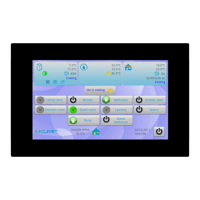
LCD Display:
The LCD provides comprehensive information:
- General Display: Shows communication status with computer/gateway, functional module, SMS module, and telephone remote control. It also indicates centralized controller locking (0.5Hz flash or constant for key locking) and remote control locking for selected air conditioners. Cooling and heating mode locking are also indicated.
- Indoor Unit Code: Displays address range 00-63 with "#" luminous.
- Indoor Temperature: Displays range 00-99°C (or 99°F), with "°C" or "°F" luminous. Invalid temperature shows "- -".
- Timing Startup/Shutdown: A flag indicates if timing is set.
- Temperature Sensors: T3, T2A, T2B values are displayed in single-machine query, with corresponding "°C" or "°F".
- Fault/Protection Codes: Displays corresponding codes in case of air conditioner fault or protection.
- Liquid Crystal Matrix: A 4x16 grid (composed of two blocks per grid) indicates the status of indoor units. Horizontal coordinates (00-15) and vertical coordinates (00+, 16+, 32+, 48+) represent the indoor unit address.
- Big Black Block: Constantly on for "In-service", slow blink for "Selected", fast blink for "Fault of indoor/outdoor unit", not bright for "Out of service".
- Small Black Block: Constantly on for "Power on", not bright for "Power off".
Maintenance Features
Filter Net Cleaning Reminding Function:
The Centralized Controller tracks its powered-on time. When this accumulated time reaches a pre-selected parameter, the controller will display "FL" (dual eight display, Fig. 2.9c) to remind the user to clear the filter. To clear this reminder, the user must manually press and hold the "SWING" key, then press the "QUERY" key. This action also resets the accumulated powered-on time of the centralized controller.
Optional Function Setting:
This feature allows for customization of certain functions. By setting dial code 3 to "ON" and powering on the controller, then pressing and holding "QUERY" and pressing "SET" within 1 minute, the user can enter the optional function setting. The display will flash with 1Hz frequency (default 00), showing optional function codes (Table 2.2). The "INC" and "DEC" keys are used to select functions, and "OK" enters parameter selection.
After entering parameter selection, the display flashes with 1Hz frequency, showing optional parameter codes. "INC" and "DEC" keys select detailed parameters. Pressing "OK" confirms the parameter selection (refer to Table 2.3 for parameter codes and corresponding times). Upon successful setting, the screen displays "Setting successfully" for 3 seconds before returning to normal display. If no operation occurs for 5 seconds during function selection, the setting parameter will not change, and the system will auto-exit. Only pressing "OK" will save the setting parameter.
This functionality allows for setting the filter cleaning reminder interval or disabling it entirely.