Do you have a question about the CLIVET TALK and is the answer not in the manual?
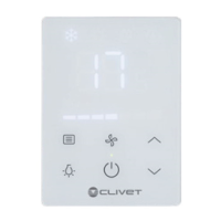
Explains the function of each button on the control keypad.
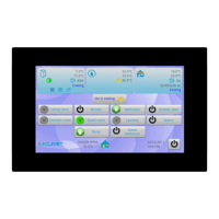
Details the elements and information shown on the main control screen.
Overview, diagram, jumpers, and I/O for the Central Module.
Overview, diagram, jumpers, and I/O for the Evaporator Module.
Overview, diagrams, jumpers, and I/O for Trio/Tandem Compressor Modules.
Outlines essential rules for configuring system modules correctly.
Explains how to set module serial addresses using DIP switches.
Details parameters for configuring system software addresses.
Table mapping DIP switch settings to hardware addresses.
Details setting the local interface address, which requires a password.
Explains how to set the address for the remote interface.
Lists and describes parameters for compressor modules.
Details parameters governing the defrost cycle operation.
Lists and describes parameters for fan control.
Covers miscellaneous system parameters.
Parameters specific to multi-compressor configurations.
Lists and describes parameters for evaporator modules.
Details parameters for pump operation.
Lists parameters for configuring system probes.
Lists central module alarm codes and their corresponding actions.
Lists compressor module alarm codes and their associated actions.
Lists evaporator module alarm codes and their associated actions.
Explains how the controller manages capacity steps based on outlet temperature.
Details calculation of temperature differences for compressor capacity control.
Describes the internal freecooling setup near the condenser coil.
Describes the external freecooling setup managed by an independent module.
Specifies conditions for starting the freecooling phase.
Specifies conditions for stopping the freecooling phase.
Explains modulation via fans and water flow.
Illustrates modulation based on evaporator outlet temperature.
Graphical representation of ON-OFF control for freecooling valve and fans.
Explains capacity step management in heating based on outlet temperature.
Details calculation of temperature differences for compressor capacity control in heating.
Describes how scan times affect step activation and deactivation.
Explains the procedure for deactivating capacity-control steps.
Modifies step activation based on exchanger temperature differences.
Adjusts offset based on critical load conditions and compressor activity.
Increases offset based on compressor running time and start frequency.
Details parameters for enabling and setting the second set point.
Describes digital input wiring for activating the second set point.
Lists parameters for Demand Limit function and reaction time.
Explains how the Demand Limit signal determines compressor availability.
Illustrates Demand Limit operation with varying compressor counts.
Lists parameters for enabling and configuring maintenance set points.
Visualizes the logic for unit operation with maintenance set points.
Describes logic for selecting compressors to balance capacity and wear.
| Category | Controller |
|---|---|
| Brand | CLIVET |
| Model | TALK |
| Protection Rating | IP20 |
| Communication Protocol | Modbus RTU |
| Power Supply | 24 V AC/DC ±15% |
| Relative Humidity | 5% to 95% (non-condensing) |