Data creazione 10/09/03 DS03I009GB--00 Pagina 7 di 59
DESCRIPTION OF THE JUMPERS
DIP1
To be defined
DIP2
Board address for CAN BUS
JUMP1
Reset board (jumper for normal operation)
JUMP2
programming (jumper for programming)
JUMP3
programming (jumper for programming)
JUMP4
CAN Bus terminator (jumper for insert terminator)
STRIP
Programming strip (pin sequence)
• +5V
• TX board
• RX board
• DTR
• gnd
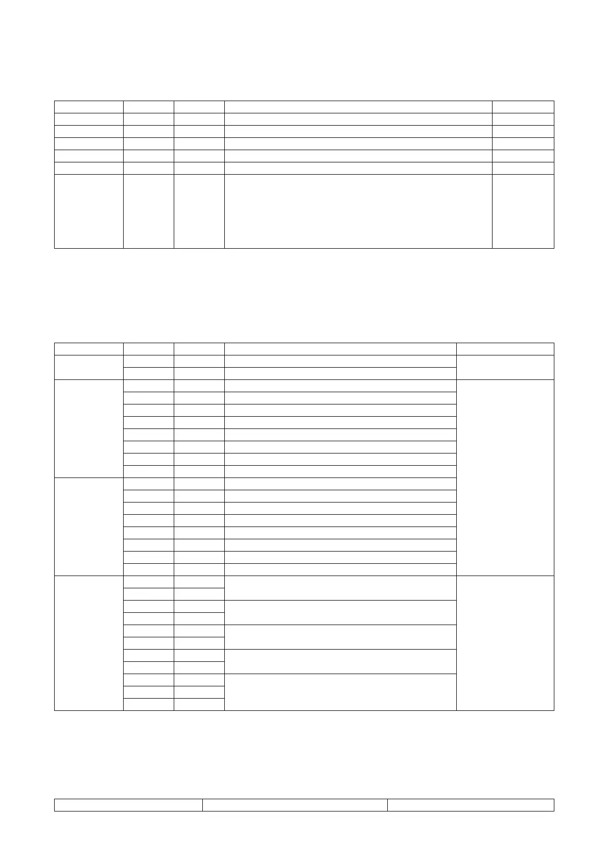
Connection of the digital inputs
I/O CLIVETTALK.LOCAL.M1
Connector Pin Terminal Description Note
J6-1
1
12Vac power (common)
J6
J6-2
2
12Vac power (reference)
Max. 6VA
J1-1
3
12V power (common)
J1-2
4
Remote On-Off input
J1-3
5
12V power (common)
J1-4
6
Remote Heat-Cool input
J1-5
7
12V power (common)
J1-6
8
Select second set point input
J1-7
9
12V power (common)
J1
J1-8
10
Mains monitor input
J2-1
11
12V power (common)
J2-2
12
Flow switch input
J2-3
13
12V power (common)
J2-4
14
Protector input pump 1
J2-5
15
12V power (common)
J2-6
16
Protector input pump 2
J2-7
17
12V power (common)
J2
J2-8
18
Check system pressure input
Max. 10mA for
each input
J16-1
19
J16-2
20
Relay 1 input
Relay 1, (pump 1 control signal)
J16-3
21
J16-4
22
Relay 2 input
Relay 2, (pump 2 control signal)
J16-5
23
J16-6
24
Relay 3 input
Relay 3, free
J16-7
25
J16-8
26
Relay 4 input
Relay 4, (freecooling control signal)
J7-1
27
J7-2
28
J16
J7
J7-3
29
Relay 5 input
Relay 5 NO, Cumulative alarms
Relay 5 NC, Cumulative alarms
5A-250V
AC1