This document describes the installation and owner's manual for the Clivet in-built controller KJRP-75A. It provides detailed information on operation, installation, and maintenance to ensure correct service and safe use of the wired controller.
Function Description
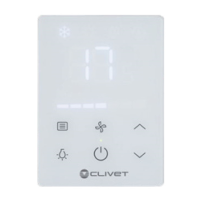
The KJRP-75A is an in-built wired controller designed to manage the operating status of an Indoor Unit (IDU). It connects to the IDU's main control board via a 5-core shielded cable. The controller allows users to set various operating parameters for the IDU through its touch keys and provides visual feedback via an LED display.
Usage Features
The controller features a user-friendly interface with several touch keys and an LED display for easy interaction.
- Display Area: The main display shows the current temperature, operating mode (Cooling, Heating, Dry, Auto), fan speed, and other indicators.
- Mode Button: Tapping this button cycles through the available operating modes: Heating, Dry, and Auto.
- Temperature Adjustment: The controller allows users to adjust the temperature within a range of 17°C to 30°C using dedicated temperature setting buttons.
- Fan Speed Button: This button enables selection from seven different fan speeds, including an "Auto" option. Note that fan speed cannot be set in Dry or Auto mode, where "Auto" will be displayed.
- On/Off Button: Used to start the unit and send all configured parameters to the IDU.
- Backlight Button: The backlight is on by default. Tapping this button turns the backlight off.
- Follow Me Function: This function is disabled by default. When activated, the controller detects the room temperature itself and sends this value to the fan coil unit every 3 minutes, overriding the temperature detected by the fan coil unit's room temperature sensor. To start or exit the "Follow Me" function, long-press the Up and Down buttons simultaneously for 2 seconds. The "Follow Me" icon on the display will turn on or off accordingly.
Supplementary Instructions:
- Backlight Mode:
- Steady On: The backlight is continuously on. Tapping any button (except the backlight and On/Off buttons) will activate this mode if the backlight is off.
- Auto Off: The backlight automatically turns off after 4 seconds. If the backlight is off, tapping the backlight button can switch it to steady on mode.
- Error Codes: The controller displays various error codes to indicate specific issues, such as:
- E7: EEPROM communication error (unit stopped, unrecoverable).
- E0: Wired controller temperature sensor port abnormal. The unit can still operate, but if "Follow Me" is enabled, E0 is displayed, and the main board is controlled by the air return port temperature. If "Follow Me" is disabled, E0 is not displayed.
- E2: Room temperature (air return port) sensor port abnormal (unit stopped, automatic recovery after clearing).
- E3: Coil sensor (T2C) port abnormal (unit stopped, automatic recovery after clearing).
- E4: Coil sensor (T2H) port abnormal (unit stopped, automatic recovery after clearing).
- E8: DC motor stall fault (unit stopped, unrecoverable).
- E9: Main board and wired controller communication error (unit stopped, automatic recovery after clearing).
- EE: Water level exceeding warning line (automatic recovery after clearing).
- PF: Model protection not set (power-on recovery after a model is selected).
- P1: Water temperature protection (automatic recovery after clearing).
- P0: Anti-freezing protection (automatic recovery after clearing).
- P2: Remote shutdown (running indicator and fault indicator act, buzzer does not, protection code is output).
Maintenance Features
The manual emphasizes several precautions for maintenance and installation:
- Power Disconnection: Before any cleaning or maintenance, it is crucial to cut off the power to prevent electrical shock.
- Cleaning: Do not use water for washing the unit. Avoid operating the unit with wet hands.
- Chemicals: Do not use pesticide, disinfectant, or flammable spray materials directly on the unit, as this can cause fire or deformation.
- Physical Handling: Do not peel off the buttons or the cover by hand to prevent electrical shock or damage.
- Professional Installation: Installation should only be performed by a distributor or qualified professionals. Users should not attempt to install or uninstall the unit randomly.
- Wiring:
- Wiring must conform to the wired controller's current requirements.
- Only specified cables should be used for wiring, and no external force should be applied to the terminals.
- The wired controller's circuit is a low-voltage circuit and should not be in contact with high-voltage circuits. It should not be arranged in the same wiring pipe as high-voltage circuits. A minimum distance of 300-500mm should be maintained between wiring pipes.
- Avoid transition or extended connections in the middle of the wire controller's wirings.
- During installation, a suitable length of connecting cable should be reserved to allow the wired controller to be taken down for maintenance.
- After connecting the terminal, any excess cable should be placed back into the hole on the wall, not left inside the wired controller.
- Temperature Detection: If the wired controller is placed in an enclosed space (e.g., a box), it may not accurately detect the ambient temperature.
The manual provides detailed instructions for both non-wall-mounted and wall-mounted installation methods, including steps for connecting the cable set, removing the rear cover, and fixing the controller. It also includes a schematic drawing of the wiring with the IDU.