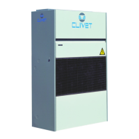
Do you have a question about the CLIVET CF-V 71 and is the answer not in the manual?
Importance of the serial number for machine identification and spare parts.
Requirement for qualified personnel for installation and maintenance.
Installation must comply with local safety regulations.
Ensuring power supply conforms to unit rating plate data.
Safety precautions before performing maintenance operations.
Importance of periodic inspections for safety and repair.
Action to take in case of faults or poor operation.
Requirement for authorized service centers for repairs.
Consequences of unauthorized modifications to the unit.
Unit designed to prevent risks to persons and health.
CE mark compliance with EC directives.
Situations beyond manufacturer control that pose risks.
Highlighting areas where only authorized personnel may operate.
Safety procedures for handling the unit to prevent falls or damage.
Risks associated with incorrect installation and precautions.
Potential risks like burning smell, smoke, or contact with components.
Risks of electric shock, fire due to improper electrical connections.
Checking unit for damage or deficiencies upon arrival.
Operation of handling the unit with safety norms and factors.
Considerations for installing air-conditioning systems.
Guidelines for unit placement, safety valves, and floor verification.
Importance of functional spaces for operation and maintenance.
Design considerations for piping and intercepting valves.
Precautions for units subject to temperatures near 0°C.
Dispersing condensate to avoid damage and prevent odors.
Preventing freeze formation in the coil and related connections.
Importance of proper air connection execution for operation and silence.
Electrical lines and components must be determined by specialized personnel.
Electrical operations must be performed by trained personnel.
Electrical data shown on the unit registration plate.
Step-by-step guide for connecting the unit to the mains power.
Controls fan speed using a 3-speed board.
Control inputs for low, medium, and high fan speeds.
Potentiometer for continuous fan speed control.
Trimmer for adjusting factory calibration of fan speed.
Connection for RS485 serial line with MODBUS protocol.
Specifications and guidelines for RS485 network connection.
Verifying installation, power supply, and safety measures.
Checking screw tightening, ground connection, and power supply.
Checking fluid temperatures, power supply, and absorption.
Checking and calibrating air flow-rate based on system characteristics.
Managing the unit locally via thermostat or remotely via RS485.
Unit has 2 set-points (heating/cooling) and regulates based on ambient temp.
Automatic, Manual, and ECO modes for unit operation.
Identifying and eliminating causes of alarms before resetting.
Table of alarm codes and their meanings.
Table listing accessible parameters with their ranges and defaults.
Table of alarm codes and their meanings.
Safety before maintenance or cleaning: disconnect power.
Caution regarding contact with coil fins and use of protective gloves.
Inspections by authorized centers or qualified personnel.
List of specific inspection checks to be performed.
Operations must be performed by qualified technical personnel.
Identify and eliminate alarm causes before resetting.
Procedure for safely disconnecting the unit by authorized personnel.
Unit must be sent to authorized centers for dismantling and disposal.
| Brand | CLIVET |
|---|---|
| Model | CF-V 71 |
| Category | Touch terminals |
| Language | English |


