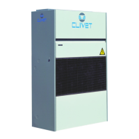
Do you have a question about the CLIVET CF-V 242 and is the answer not in the manual?
Specifies the need for qualified technicians and adherence to local safety regulations.
Highlights additional safety measures and the unit's designated purpose for civil air-conditioning.
Identifies specific danger zones and outlines general risks associated with unit operation.
Details risks during unit handling and potential hazards from incorrect installation.
Covers risks related to improper electrical connections, grounding, and component covers.
Warns about hazards from moving fan parts and potential water system leaks or damage.
Provides detailed instructions and considerations for safe unit handling operations.
Guidelines for optimal unit positioning, functional spaces, and avoiding flooding.
Precautions against freezing and requirements for insulating water tubes.
Recommendations to prevent ice formation within the water heating coil, even in summer.
Emphasizes requirements for electrical lines and operations by qualified personnel.
Provides unit electrical data and a step-by-step guide for connecting to the mains power.
Provides optimal placement guidelines for room thermostats to ensure accurate readings.
Information on establishing BMS communication via RS485 serial lines.
Essential checks for installation, power supply, and system readiness before start-up.
Detailed checks for air, water, and electrical systems to ensure proper operation.
Verifying voltage, absorption, and set-points after initial checks.
Explains visible alarm codes and the importance of identifying causes before resetting.
Stresses the need for qualified personnel and proper alarm identification before resetting.
| Brand | CLIVET |
|---|---|
| Model | CF-V 242 |
| Category | Touch terminals |
| Language | English |


