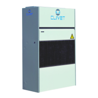
Do you have a question about the CLIVET CF-V 91 and is the answer not in the manual?
Details about the unit identification label including type, serial number, and manufacturer.
Importance and use of the unit's serial number for tracing and identifying specific features.
Identifying danger areas around the unit and safety procedures for handling and maneuvering.
Risks associated with incorrect installation and general operational hazards like smells or smoke.
Hazards related to improper electrical connections, grounding, and components.
Risks from contact with moving parts and water leaks due to system defects.
Procedures for checking unit damage during transit and guidelines for proper storage.
Measures to prevent freezing in water connections and the unit in low temperatures.
Step-by-step guide for connecting the unit to the power supply.
Essential checks for preliminary, aeraulic, water, and electrical systems before startup.
Verifying voltages, absorptions, remote inputs, and setting operational set-points.
Procedure to verify and calibrate unit air flow rate against system characteristics.
Logic for switching between cooling and heating modes based on temperature.
Codes for alarms and malfunctions displayed by the unit.
Procedure to access and modify unit parameters for calibration and configuration.
Importance, frequency, and procedure for cleaning/replacing air filters.
Recommended frequency and scope of maintenance inspections for unit components.
General guidelines for resolving alarms and troubleshooting unit issues.
Procedures for safely disconnecting the unit and recovering refrigerant/antifreeze.
| Category | Touch terminals |
|---|---|
| Model | CF-V 91 |
| Brand | CLIVET |
| Cooling Capacity | 9.1 kW |
| Heating Capacity | 10.2 kW |
| Power Supply | 230V/1Ph/50Hz |


