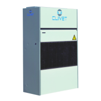
Do you have a question about the CLIVET CF-V 142 and is the answer not in the manual?
Unique identifier for the machine, crucial for tracing features and ordering spare parts.
Defines external and internal danger zones around the unit where authorized personnel may operate.
Stresses the need for safety procedures during unit handling to prevent falls or toppling.
Warns about risks of incorrect installation, including leaks, shocks, fire, and damage.
Covers risks like burning smells, contact with components, unskilled repairs, and panel security.
Details risks associated with power supply, wiring, grounding, and exposed live parts.
Warns about injury from contact with fan rotors and emphasizes safety procedures before access.
Addresses risks of leaks from pipelines or components and the importance of secure hydraulic connections.
Advises on measures to prevent freezing of water connections and the unit.
Stresses that electrical work requires specialized personnel and adherence to diagrams.
Outlines the steps for safely connecting the unit to the electrical power supply.
Lists essential checks before starting unit operation, including installation and power supply.
Details checks for air filters, ducting, dampers, and diffusers for proper airflow.
Outlines checks for plumbing, water circuit filling, pressure, and shut-off valves.
Specifies checks for electrical connections, grounding, and power supply parameters.
Guides on checking fluid temperatures, working limits, and unit absorptions during operation.
Explains unit management via thermostat or RS485 serial line with MODBUS protocol.
Lists and explains various alarm codes generated by the unit's electronic system.
Describes the procedure for accessing and modifying unit parameters via the thermostat.
Provides a comprehensive list of thermostat parameters, their ranges, units, and default values.
Lists and explains alarm codes for unit malfunctions and communication issues.
Details the importance of clean air filters for unit efficiency and hygiene, with cleaning procedures.
Recommends inspection frequency and lists key inspection points for unit components and circuits.
Emphasizes identifying and eliminating the cause of alarms before resetting to prevent damage.
Details procedures for safely disconnecting the unit, recovering refrigerant and antifreeze.
Instructs to send the unit to authorized centers for dismantling and disposal, complying with regulations.
| Brand | CLIVET |
|---|---|
| Model | CF-V 142 |
| Category | Touch terminals |
| Language | English |


