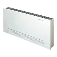
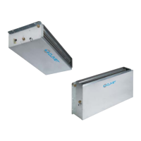
Do you have a question about the CLIVET ELFORoom 2 011.0 and is the answer not in the manual?
Information for the user, including manual placement and breakdown procedures.
Information on locating and understanding the serial number label.
Procedures for checking the unit upon delivery for damage or anomalies.
Requirements for functional spaces around the unit for operation and maintenance.
Guidelines on where to avoid installing the unit.
Guidance on selecting an optimal location for the ambient thermostat.
Instructions for horizontal or ceiling mounting of the unit.
Guidance on choosing and sizing hydraulic lines and making connections.
Requirements and procedures for condensation discharge.
Specific instructions for vertical condensation discharge.
Information on obtaining electrical data from the serial number label.
Steps for making electrical connections to the unit.
Overview of the ELFOSystem GAIA Edition system components.
Wiring diagram for HID-E2 thermostat (4 pipe system).
Wiring diagram for HID-E3 thermostat (2 pipe system).
Explanation of the board's LED status and alarm codes.
Operation and functions of the built-in electronic thermostat.
How to set manual ventilation and fan speeds.
Overall technical specifications for cooling, heating, and air handling.
Guidelines for dismantling and proper disposal of the unit.
| Brand | CLIVET |
|---|---|
| Model | ELFORoom 2 011.0 |
| Category | Touch terminals |
| Language | English |


