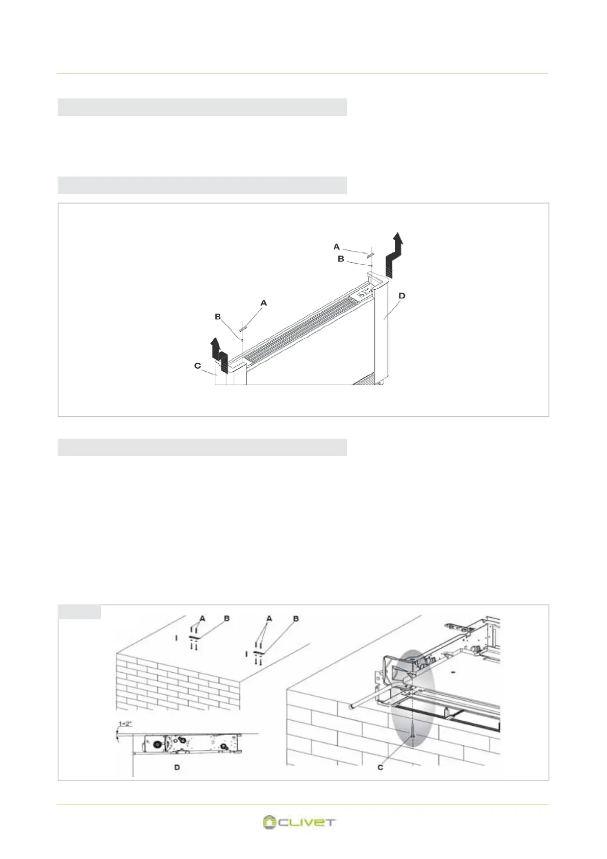
3.6 HORIZONTAL OR CEILING INSTALLATION
x Using the paper template, trace on the ceiling the position of the two fixing brackets and the two rear screws.
x Using a suitable drill, make the holes and insert the toggle bolts (2 for each bracket) (fig. 3.1 ref. A); fix the two brackets (fig. 3.1
ref. B). Do not over-tighten the screws.
x Position the machine on the two brackets, keeping it in position and then fix the two screws into the rear toggle bolts (fig. 3.1 ref.
C), one on each side.
x Make sure that there is sufficient inclination of the unit towards the drainage pipe to facilitate the water drainage (fig. 3.1 ref. D).
x Fully tighten all 6 fixing screws.
3.5 SIDE OPENING
3 - POSITIONING
The following descriptions of the various mounting phase and the relative designs refer to a version of the machine with fixtures on the
left. The operations for the mounting of machines with fixtures on the right are exactly the same
.
Only the images are to be considered as a mirror image.
3.4 INSTALLATION
fig 3.1
x lift A
x unscrew B
x move to the left C
x lift C
x lift A
x unscrew B
x move to the right D
x lift D
M09160D17-02 57
 Loading...