Do you have a question about the CLIVET ELFODuct MP Series and is the answer not in the manual?
Provides correct unit installation, use, and maintenance. Pay attention to warnings and prohibited operations.
Only qualified personnel can operate on the unit, as required by regulation.
Unit designed to prevent injuries; residual risks are detailed. Inexperienced personnel may cause damage.
Use the unit only for civil air-conditioning and within specified limits. Manufacturer not responsible for other uses.
Positioning, hydraulics, electrics, and ducting determined by designer. Follow local regulations and verify electrical line characteristics.
Plan periodic inspection and maintenance to avoid or reduce costs. Turn off unit before operation.
All unit modifications will end the warranty coverage and the manufacturer's responsibility.
Disable unit immediately in case of breakdown. Use original spare parts only. Using unit during malfunction voids warranty.
Installer must train user on start-up, set points, standby, maintenance, and breakdown procedures.
Product improvements may imply manual data changes. Visit manufacturer website for updated data.
Keep manual accessible. Note unit data label for assistance. Provide unit notebook for interventions.
Serial number label identifies unit features. Matriculation plate must not be removed and shows unit type, serial number etc.
Identifies each unit uniquely. Must be quoted when ordering spare parts.
Note data from the serial number label for easy reference when needed.
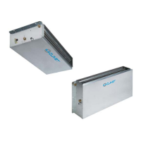
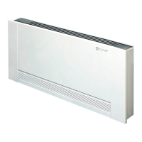
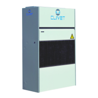
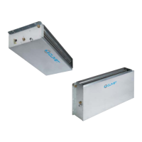
Details four types of units: horizontal rear intake, horizontal floor inlet, vertical floor inlet, and vertical front inlet.
Observe external packaging instructions for storage.
Verify unit weight, identify critical points, protect unit, do not leave packages loose, do not move alone, use suitable containers for multiple units.
Be careful not to damage the unit. Keep packing material away from children. Recycle and dispose of packaging according to regulations.
Functional spaces ensure good operation, maintenance access, and protection. Double spaces if units are aligned.
Units are for internal, fixed positions. Do not install outdoors or in rooms below 0°C. Limit vibration transmission.
Choice of location is essential for comfort and energy. Place thermostat in a room with representative conditions, 150cm high, preferably on an internal wall.
Selection and installation of components like cut-off valves, thermometers, manometers, air bleed valve, drainage taps.
Sequence for tightening operations, hydraulic connections, leakage test, isolation, and venting.
Dispose condensate to avoid damage. Provide siphon, ensure duct slope, anchor ducting, insulate duct and siphon, connect to sewerage.
Prevent freeze risk by safeguarding pipes, insulating, draining if unused, or providing antifreeze resistance.
Refers to page 49 for fixture rotation instructions.
Internal channel surface must be smooth, washable, and non-contaminating. Thermally isolate channels to avoid energy losses.
Serial number label reports unit specific electrical data. Matriculation plate shows voltage, FLA, FLI, wiring diagram number.
Refer to electrical diagram. Verify supply characteristics. Ensure unit is isolated, earth connected, and cables protected.
Do not exceed max power. Lay cables far from power cables and interference sources. Cross cables at 90°.
Lists remote controls and their corresponding page numbers.
Lists room control units and their corresponding page numbers.
Refers to page 45 for mini-network details.
Operations done by qualified technician. Agree start-up data with service centre. Verify unit installation and power supply.
Checks include safety access, functional spaces, air flow, structure integrity, fan operation, vibration isolators, filters, aeraulic system, earthing, and power supply.
Sequence for unit ON power supply: voltage measure, fan check, air flow rate, temperature measurement, vibration check, and documentation.
Ensure hydraulic system is clean, filled, pressurized, and air-free. Check shut-off valves are open.
Verify ground connection and conductor tightening. Check voltage and frequency values.
Check air/water temperatures within limits. Check voltage and absorptions under stable operating conditions.
Check remote controls and optional components are connected and enabled.
Identify operating conditions: voltages, absorptions, temperatures, and pressures for control and maintenance.
Maintenance by authorized centers or qualified personnel. Allows maintaining efficiency and increasing lifespan. Verify safety checks.
Perform inspection every 6 months minimum. Frequency depends on use; plan shorter intervals for frequent or critical use.
Create a unit booklet to note interventions, including date, type, description, and measures.
If long inactivity: turn off power, avoid frost risk (empty system or add glycol). Re-start by qualified technician.
Checklist for maintenance items like corrosion, panel/fan fixing, coil/bowl cleaning, filters, air flow, wiring, earthing, power supply, and protective devices.
Clean exchanger fins with protective gloves. Remove dust/deposits using air pressure or vacuum cleaner. Check fins for damage.
Clean basin periodically to prevent clogging and microorganism growth. Pour water to check outflow.
Check cleaning state, fastening, and presence of corrosion for electric heaters.
Clean/replace filters for maximum thermal exchange and hygiene. Clogged filters reduce air flow. Frequency varies weekly to monthly.
Troubleshooting guide for common issues like feeble air discharge, excessive noise, motor/fan failure, heating/cooling issues, water entrainment, and condensate.
Only authorized personnel should disconnect. Avoid leaks. Recover refrigerant gas and anti-freeze solutions.
Send unit to authorized centers. Recover or dispose of materials according to national standards. Contact manufacturer for details.
Units comply with Directive EC on waste electrical and electronic equipment. User must not dispose of unit as urban waste.
Indicates common situations not controlled by manufacturer that pose risks to people or things.
Area accessible only to authorized operators, inside the unit, requiring deliberate removal of protections.
Improper handling can cause drops or tipping, leading to damage. Follow manual instructions and local regulations.
Incorrect installation can cause leaks, electric shock, or poor operation. Ensure qualified personnel and adherence to regulations.
Smell of burning, smoke, or anomalies may indicate serious issues. Electrically isolate unit. Accidental contact with components may cause injuries.
Incomplete/incorrect electrical connections can cause shock, damage, or fires. Ensure proper earthing and component fixing.
Contact with transmissions or fan aspiration can cause injuries. Isolate unit before entering. Ensure fans are properly guarded.
Tubing defects or removal may cause leaks or water projection, leading to damage or short circuits.
Provides diagrams and dimensions for horizontal concealed units in a 2-pipe system, including water fittings and supply.
Provides diagrams and dimensions for vertical concealed units in a 2-pipe system, including water fittings and supply.
Provides diagrams and dimensions for horizontal concealed units in a 4-pipe system, including water fittings and supply.
Provides diagrams and dimensions for vertical concealed units in a 4-pipe system, including water fittings and supply.
Technical data for 2-pipe system: cooling/heating capacity, internal exchanger, fans, connections, power supply, and noise levels.
Presents sound power and pressure levels in dB(A) for minimum, medium, and maximum fan speeds across different sizes.
Graph showing pressure drops related to water flow rate for exchanger performance.
Technical data for 4-pipe system: cooling/heating capacity, internal exchanger, fans, connections, power supply, and noise levels.
Presents sound power and pressure levels in dB(A) for minimum, medium, and maximum fan speeds across different sizes.
Graph showing pressure drops related to water flow rate for exchanger performance.
Details electrical accessories for remote controls, room thermostats, and electronic controls.
Describes electromechanical room thermostat functions: setting temp, speed selection, ON/OFF, ventilation, summer/winter change, valve control.
Describes room thermostat functions: auto fan speed, silent operation, ON/OFF, ambient temp adjustment, auto season change, hot start, destratification.
Describes electro-mechanical thermostat for wall mounting with proportional outlets for 2 or 4 pipe systems, allowing temp setting and fan speed selection.
Allows interface with regulation module, managing units. Functions include setting temp, fan speed, ON/OFF, season change, economy mode, diagnostics.
Allows interface with regulation module. Functions include setting temp, fan speed, ON/OFF, season change, economy mode, humidity control, diagnostics.
Allows interface with regulation module. Functions include setting temp, fan speed, ON/OFF, season change, economy mode, ventilation-only mode, diagnostics.
Lists HIDT2X and HIDT3X electronic room controls for wall mounting.
Explains the thermostat display icons for Set Point, REMOTE, ECO, AUTO, visible states, and ventilation status.
Unit can be managed locally via thermostat or remotely via RS485 serial line with MODBUS protocol.
Unit can be switched on/off by thermostat, digital input, or net.
Unit has 2 set-points (heating/cooling). Operates based on water temperature (Winter > 30°C, Summer < 20°C).
Modules automatically switch between cooling/heating based on entering water temperature or return air.
Manually choose cooling or heating mode using relevant keys. Set P31 parameter to 0.
Economic operation saves energy. ECO setpoints are adjusted for comfort vs. energy saving.
Fan speed is set manually, but unit regulates temperature based on AUTO, MANUAL, or ECO modes.
Maximum fan speed is self-limited for reduced noise, especially during night operation.
Describes automatic mode change for 2-pipe units based on water temperature and a neutral zone.
Allows displaying ambient temperature measured by thermostat or unit probe. Alternates with 'tA' for a few seconds.
Lists alarm codes displayed by the terminal unit, including RES, FES, BT1, BT2, BT3, H20, SLF, CO, EHH, SYS, ERR, EUR.
Before resetting, identify and remove alarm causes to prevent irreversible damage. Ask authorized centre for doubt.
Access to parameters is for calibrations and configurations by authorized centers or technicians. Describes key combinations to access parameters.
Lists parameters like working band, water temperatures, time settings, fan status, mode settings, and probe calibration.
Describes the flush-mounted thermostat for remote control of units, allowing settings for humidity, temperature, ventilation, and diagnostics.
Details the functions of the keys: operating mode selection, increase/decrease selected field, and ON-OFF/confirm.
Explains display icons: REMOTE, ECO, AUTO, BAT, BLC, and their corresponding meanings.
The HID-TI2/T13 thermostat is for recessed installation, not a MODBUS thermostat. Allows setting humidity, temperature, ventilation, and diagnostics.
Describes 'Normal' operation (connected to CLIVET-BUS) and 'Nolink' operation (without CLIVET-BUS connection).
Procedure for initial reset using battery and power key, or upon connection to CLIVETBUS.
User programming allows choosing mode, setting point, managing fan speed, enabling/disabling swing, displaying temp, power on/off, and activating silenced mode.
Press and hold the [4] key to power on/off the unit. 'OFF' status is indicated by the message OFF.
Press key [1] to show operating mode symbols. Press [1] again to select mode (Heating, ECO, Cooling, ECO, Ventilation). Confirm with [4].
In normal operation, modify set point using keys [2] and [3] to increase/decrease in steps of 0.1°.
Details on managing fan speed.
In VENTILATION MODE, temperature adjustments are not made; fan speed can be changed.
Explains how to select fan speed and switch between automatic and manual modes.
Explains fan speed setting is not cyclical and indicated by a flashing bar.
Activate/deactivate silenced mode by pressing key [4]. Indicated by 'SIL' message.
Displays ambient temperature from thermostat or unit. Alternates with 'tA'. Press [4] to confirm, or [1] to go back.
Activate/deactivate Swing function by pressing keys [1] and [2] simultaneously.
Device checks battery charge on power-on or disconnection. Message 'BAT' appears if battery is low.
Lists alarm codes displayed by the unit: RES, FES, BT1, BT2, BT3, H20, SLF, CO, EHH, SYS, ERR, EUR.
Details hidden buttons for installer use: thermostat starting/reset, filter hiding, self-addressing, parameter access, keypad lock.
Ventilation is activated if water temperature is below P02 MaxH2oCool or ambient temperature.
Ventilation is activated if water temperature is above P03 MinH2Oheat.
Fan speed is proportional to the difference from the set point. Max speed in summer/winter based on temperature.
System controls 2 ON-OFF valves for heat and cold. Valve opens when thermo-regulator requests power.
Defines electric resistance operating modes (integration, main element) and types (single-phase, two-phase, 0-10 volt).
Allows activation of a damper or fan for fresh air intake using a dedicated output.
Dehumidification control managed by network. Unit forced into cooling mode if DeumiOn variable is 1. Stops if conditions are met or unit is OFF/Heating.
Disables user keys. Press key [11] to activate/deactivate. Message 'bLC' is shown. Pressing keys has no effect.
Terminal units must be networked by a serial converter. Details addressing RS-485 MODULE via S3, S4, S5.
General indications for RS 485 serial line, including cable type, number of components, length, and installation by trained personnel.
Details shielded cable specifications and serial line installation requirements for RS485 communication.
Explains the need for termination resistors to prevent or attenuate interferences on the signal.
Thermostats are not part of the network and connect directly to the terminal unit.
Describes mini-network configuration: master/slave units, settings, and communication parameters.
Master units send controls to slave units. Slave units use their own water probe. Keyboards on slaves are for display only.
Thermostat displays alarms for the master unit. Slave units display their own alarms if equipped with a keyboard.
Status and parameters displayed by the thermostat are relevant to the Master unit.
Digital inputs can be configured for ON-OFF events or alarms, relevant to the unit or network.
Units operate in stand-alone mode with local settings if the network is absent.
Master unit broadcasts controls and settings. Lists parameters and their notes for network configuration.
Declaration of conformity with EC directives, including machinery, EMC, and pressure equipment directives.
Instructions for reversing hydraulic connections on vertical units, involving panel removal and component reinstallation.
Step-by-step guide to reverse the coil orientation, including screw removal, panel placement, and closing open holes.
| Brand | CLIVET |
|---|---|
| Model | ELFODuct MP Series |
| Category | Touch terminals |
| Language | English |