9
4 - WATER CONNECTIONS
4.4 CONDENSE DRAIN
The condense must be disposed of in order to avoid
damaging things and persons.
• Unit drain coupling: the connection must not transmit
mechanical stresses and must be carried out paying
attention not to damage the unit drain coupling.
• Foresee a siphon that, by eliminating the depression
caused by the fan, prevents suction of air from the drain
piping.
• The piping must have adequate slope to allow out flow.
• Anchor the piping with an adequate number of supports.
• On the contrary, cracking in the piping and air pockets
obstructing the outflow, are generated.
• Isolate piping and siphon to avoid condense dripping.
• Connect the condense drain to a rain drain network.
• DO NOT use white waters or sewage drains to avoid
possible inhaling of odours in case of evaporation of the
water contained in the si phon.
• At work end, check the regular outflow of the condense by
pouring water in the bowl.
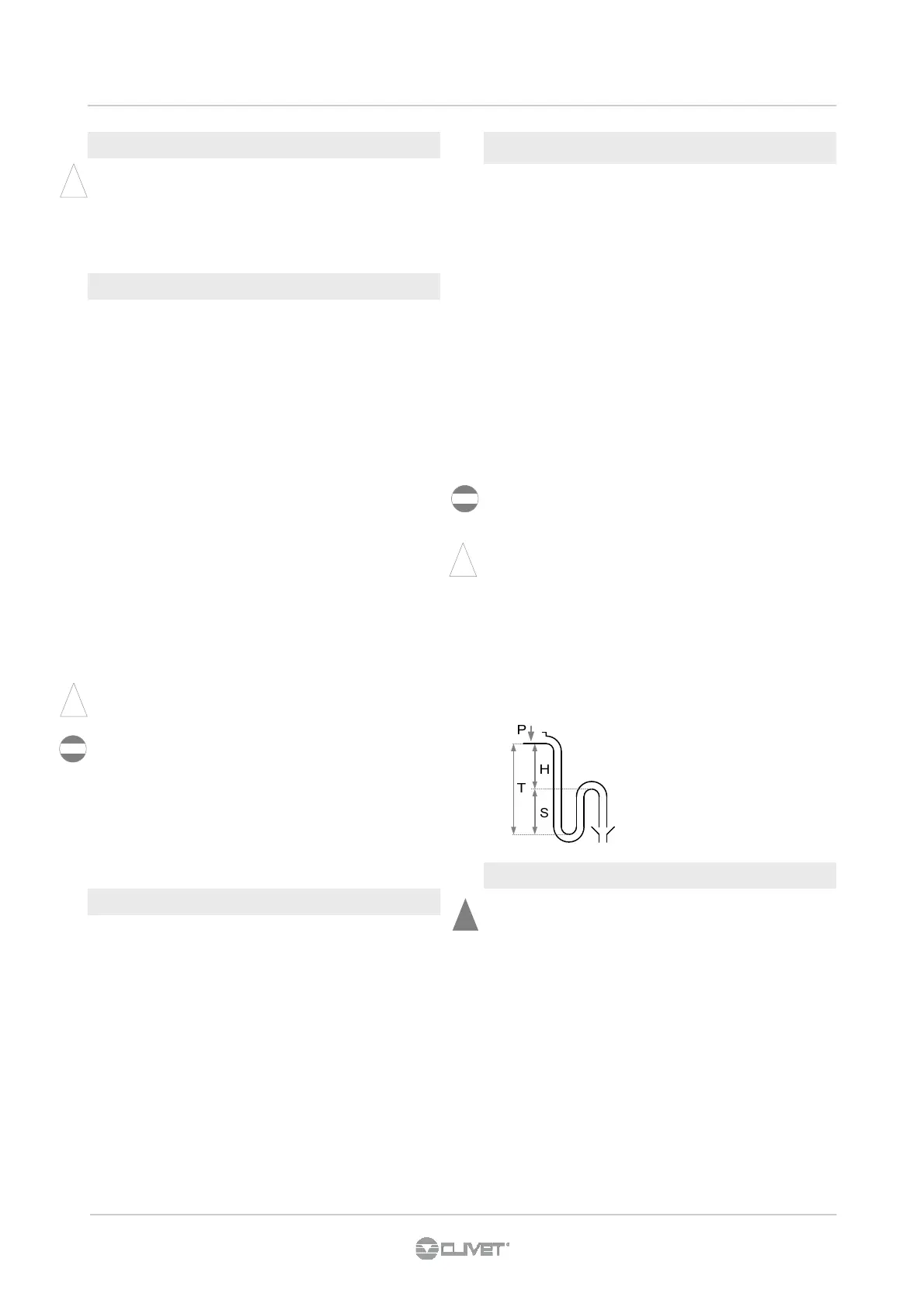
i
Example :
P = 300 Pa = 30 mm
T = 2P = 60 mm
S = T/2 = 30 mm
Siphon height calculation
T = 2P
S = T/2
P is the pressure determined by the fan in correspondence of
the condense collection bowl (approx. 1 mm = 9.81 Pa)
4.1 PRELIMINARY INFORMATION
Selection and installation of system components must be
carry out by installer.
Following a series of instructions that must be integrated with
what required by local regulations and by the code of practise.
INTERCEPTING VALVES
• Installed on the input and output, they allow to carry out all
the maintenance operations and possible without emptying
the installation.
THERMOMETERS AND PRESSURE GAUGES:
• Installed on the input and output of the main parts facilitate
the controls and the maintenance.
BLEED VALVES :
• Installed in all the highest points of the system, they allow
the venting from the circuit.
BLEEDING COCKS :
• Installed at the lowest points of the circuit, so as to allow
emptying .
EXPANSION TANK :
• It allows the system correct pressure to be maintained at
the water temperature changing. It has to be sized
according to the system water content.
WATER FILTER :
• If it is not built-in, it has to be immediately installed at the
unit water inlet, in a position easily accessible for cleaning.
• The filter should never be removed, the operation will void
the warranty.
SUPPORTS :
• for the weight of the water piping that must not rest on the
unit fittings.
FLOW SWITCH
• as a component of the system must always be provided.
4.2 COMPONENTS
4.3 OPERATION SEQUENCE
Before connecting the unit, carefully wash the system by filling
it and emptying it several times with clean water.
Ignoring this operation will lead to several filter cleaning
interventions and at worst cases can cause damages to the
exchangers and the other parts.
Execute leakage test before isolate the pipes.
To avoid heat dispersions and formation of condensate isolate
all the pipes.
Leave various point of service free (wells, vent-holes etc )
i
i
Adopt measures to prevent risk of freezing if the unit or
relative hydraulic connections can be subject to temperatures
near 0°C.
• isolate the piping
• protect the piping with heating cables laid underneath
the insulation
4.5 RISK OF FREEZING
!