Branch header must be connected with indoor units directly,
the further branch connection is not allowed.
Select branch joint
Select the branch joint according to the total designed capacity
of indoor units which it connects to. If this capacity is more than
that of the outdoor unit, then select the connection according to
the outdoor unit.
The selection of branch header depends on the quantity of
branches it connects to.
9 12 50%~130%
Outdoor Unit
(kW)
Capacity of
Outdoor unit
(horsepower)
Maximum
Quantity of
Indoor unit
Sum Capacity
of Indoor unit
(horsepower)
0.8
1.3
1.6
2
2.8
3.5
4.5
5
22
0.618
100
4112
3.290
36
45
56
2.571
125
4.3120
140
80
Capacity
ranking
Capacity
(horsepower)
Capacity
ranking
Capacity
(horsepower)
Connection method
Welding or Flaring
Flaring
Branch pipe
Indoor unit
20kW
22.4kW
26kW
Air side
Liquid side
Table 4-9
Table 4-5
Piping sizes at the branch pipe
128
Flaring
Welding or Flaring
Welding or Flaring Welding or Flaring
Welding or Flaring Welding or Flaring
Welding or Flaring Welding or Flaring
Table 4-10
When outdoor
unit is top
When outdoor
unit is bottom
less than 10
MODEL
(kW)
The max height drop(m)
The length of
refrigerant
pipe(m)
The number
of bends
When the outdoor unit connects one indoor unit
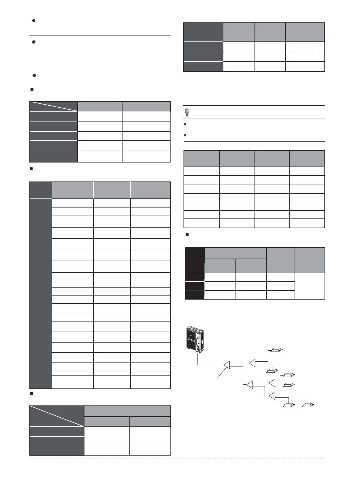
4.6 Illustration
Outdoor Unit((Take Model 260 for example)
Caution: Suppose in the displayed piping system, the total equi-
valent piping length of air side + liquid side is longer than 90m.
20
22.4
26
25
25
20
20
50
25
20
50
50
50%~130%
50%~130%
10
11
7
8
Table 4-8
Fig.4-6
Piping connection
side
ĭ22.2 ĭ9.5
Pipe diameter of outdoor unit's connector(mm)
ĭ19.1 ĭ9.5
Model(kW)
20
22.4
26
Table 4-7
Pipe diameter of the connector in the outdoor unit's body
Gas Side Liquid Side
20
22.4
26
When capacity of indoor unit greater than the sum of 100%, capacity
of indoor unit will be attenuated.
When capacity of indoor unit greater than or equal to the sum of
120%, in order to ensure the effectiveness of machine, and then try to
open the indoor units at different time.
NOTE
The indoor unit capacity total can not exceed 130% of the outdoor
unit load.
Overloading reduces the corresponding capacity.
The first line Branch Pipe
1
1
1
1
1
1
Indoor unit
$
%
'
(
&
D
E
F
H
I
G
/
/
/
/
/
Four-sided air outlet
56~80
Four-sided air outlet
28~45
Wall mounted 22~45
Thin duct type 71
12.7(Flaring nut)
12.7(Flaring nut)
15.9(Flaring nut)
15.9(Flaring nut)
6.4(Flaring nut)
Wall mounted 56 15.9(Flaring nut) 9.5(Flaring nut)
6.4(Flaring nut)
9.5(Flaring nut)
9.5(Flaring nut)
One-sided air outlet
18~45
12.7(Flaring nut) 6.4(Flaring nut)
One-sided air outlet
56
15.9(Flaring nut) 9.5(Flaring nut)
Low static pressure
18~45
12.7(Flaring nut) 6.4(Flaring nut)
Low static pressure 56
15.9(Flaring nut) 9.5(Flaring nut)
A5 duct type 22~45
A5 duct type 56~140
12.7(Flaring nut) 6.4(Flaring nut)
Refrigerant
R410A
A (TYPE) Air Side (ĭ) Liquid Side (ĭ)
Table 4-6
(A: the total capacity of indoor units)
Four-way Cassette Type
15~45
12.7(Flaring nut) 6.4(Flaring nut)
Tow-way Cassette Type
22~45
12.7(Flaring nut) 6.4(Flaring nut)
Tow-way Cassette Type
56~71
15.9(Flaring nut) 9.5(Flaring nut)
Console Type 22~45
12.7(Flaring nut) 6.4(Flaring nut)
Ceiling And Floor Type
36~45
12.7(Flaring nut) 6.4(Flaring nut)
Ceiling And Floor Type
56~160
15.9(Flaring nut) 9.5(Flaring nut)
Expose And Concealed
Floor-standing type 22~45
Expose And Concealed
Floor-standing type 56~80
12.7(Flaring nut) 6.4(Flaring nut)
15.9(Flaring nut) 9.5(Flaring nut)
15.9(Flaring nut) 9.5(Flaring nut)
00$1 06$1;0L77 ,QVWDOODWLRQPDQXDO
 Loading...