38
Electrical connections
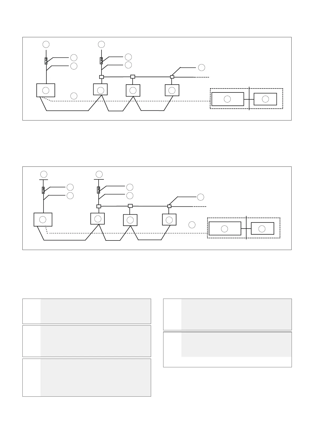
Controller connection - 8 ~ 16 kW single phase
Fig. 61
A Power supply 220-240 V ~ 50 Hz single phase / 208-230 V
~ 60 Hz single phase
B Switch / Power switch
C External electrical connection
D Internal electrical connection
E Electrical distribution box
F Outdoor unit
G Indoor unit
H Communication bus
I Central control monitor
L Computer
Controller connection - 10.5 ~ 18 kW single phase
Fig. 62
A Power supply 380-415 V ~ 50 Hz three phase / 380-415 V ~
60 Hz three phase / 208-230 V ~ 60 Hz three phase
B Power supply 220-240 V ~ 50 Hz single phase / 220-240 V
~ 60 Hz single phase / 208-230 V ~ 60 Hz single phase
C Switch / Power switch
D External electrical connection
E Internal electrical connection
F Electrical distribution box
G Outdoor unit
H Indoor unit
I Communication bus
L Central control monitor
M Computer
a
CAUTION
Select the power supply source for the indoor
unit and the outdoor unit respectively.
a
CAUTION
The power supply must come from a branch
circuit complying with the specifications, with
leakage protection and a manual switch.
a
CAUTION
For outdoor unit models with dierent power
supply types, refer to the unit’s data plate.
(Connect all power supply lines of indoor units
in the same system to the same branch circuit.)
a
CAUTION
Lay the electrical connections between the
indoor and outdoor units together with the
refrigerant lines.
a
CAUTION
Use 3-wire (3X0,74mm2) shielded cables for
the signal lines
of the indoor and outdoor
units.
A
B
C
F G
H
G G
I L
B
D
E
A
Fig. 61
PQE
C
D
C
E
G
H
H H
I
L M
F
A B
PQE
 Loading...