18
5 - ELECTRICAL CONNECTIONS
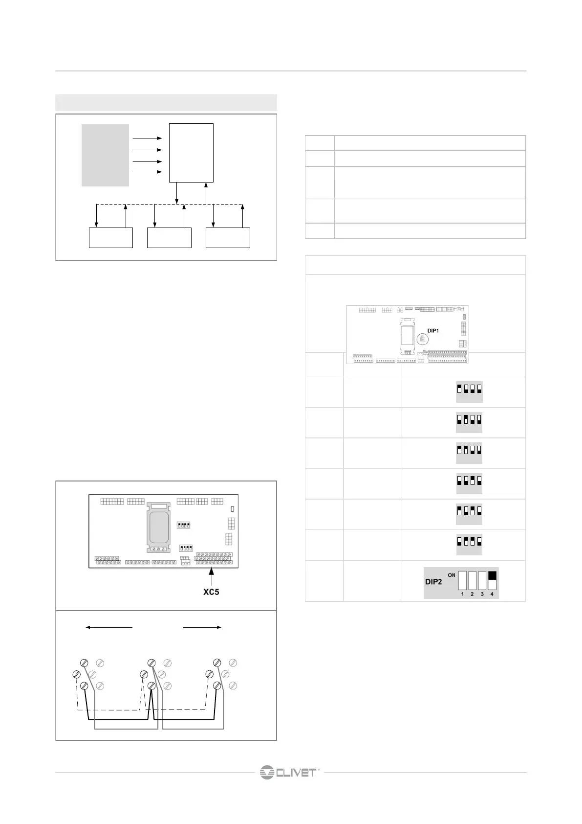
Mininet unit addressing through DIP1
num. UNIT' DIP 1
1 master
2 slave
3 slave
4 slave
5 slave
6 slave
2 .. 6 slave
num. Parameter description
343 N. of units connected in Mininet
344
N. of units in standby for rotation : it allows to keep
one or more units in standby (automatic rotation)
345
Enables the exclusion of the unit in alarm
(1=enabled)
346 Offset between the unit SetPoint
Mininet configuration parameters :
CONFIGURATION menu > UNIT > MININET
5.13 MINI-NET
1. max : 1 master + 5 slave
2. Perform the electrical connections as indicated in the
diagram
3. Set the DIP1 on the master unit
4. Set the DIP1 on the slave units
5. Set the DIP2 - SW4 on the slave units
6. Switch on and off the master unit
7. On the master become visible the mininet parameters
8. Set the parameters on the master unit
C controls
S signaling
ON-OFF
Heat-Cool
Setpoint
Water Reset
Demand Limit
MASTER
SLAVE SLAVE SLAVE
SC SSC C
C
C
S
37
19
1
38
20
2
37
19
1
38
20
2
37
19
1
38
20
2
UNIT 1
UNIT 2
UNIT ...6
XC5 XC5 XC5
MAX 200 mt
Electrical connections
For the cable characteristics see MODBUS
RS485
 Loading...