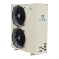
Do you have a question about the CLIVET WSAN-XPR 51 and is the answer not in the manual?
Details the serial number label on the unit, listing type, serial number, year, and data.
Explains the importance of the serial number for tracing unit features and ordering parts.
Describes the cooling cycle in SUMMER and WINTER modes, explaining heat transfer.
Stresses that installation, testing, and maintenance must be by qualified personnel.
Requires installation to adhere to local safety regulations.
Ensures power supply conforms to the unit's rating plate data.
Recommends periodical checks for loose/broken parts to prevent damage and injury.
Instructs to switch off the unit in case of faults or poor operation.
States repairs must be by authorized centers using original spare parts.
Warns that unauthorized modifications void the warranty and may cause issues.
Specifies the unit's intended use for cooling/heating water or water/glycol mix.
Highlights the unit's design to prevent risks and advises referring to "Residual Risks".
Highlights areas where only authorized personnel may operate, defining internal/external zones.
Details risks of incorrect installation (leaks, shocks, fire) and stresses qualified technicians.
Covers risks like burning smells, contact with hot components, unskilled repairs, and open panels.
Covers risks of refrigerant gas release, contact with flames, and general refrigerant safety.
Details risks from hydraulic connections and advises ensuring secure connections.
Provides safety information for R-410A refrigerant, including identification, hazards, and first aid.
Checks the unit for damage and completeness upon arrival and reporting issues.
Outlines safe handling operations, considering critical points and lifting capacities.
Lists factors for installing air-conditioning systems, like technical spaces and connections.
Stresses respecting functional clearances for good operation and maintenance access.
Details requirements for outdoor installation, safety valves, ground clearance, and antivibration.
Provides precautions against freezing for the unit and water connections, including glycol use.
Emphasizes the importance of water quality and using filters to prevent exchanger damage.
Highlights the need for a flow switch to ensure unit shutdown if water is not circulating.
Recommends using unfreezable liquids for temperatures below +4°C to prevent ice formation.
Advises verifying electrical feed for antifreeze resistances during unit stops.
Manages condensation during winter operation to avoid wetting pedestrian areas.
Stresses that electrical work must be by specialized personnel and conform to regulations.
Details the steps for connecting the unit to the main power supply.
Lists checks like proper installation, power supply, cleanliness, and ventilation.
Covers checking screw tightness, ground connection, panel repositioning, voltage, and phase unbalance.
Explains the thermoregulation based on outlet temperature and head step for resource insertion.
Explains the maintenance mode for keeping plant within limits when unit is OFF or STANDBY.
Illustrates the procedure for modifying parameters using the keypad.
Stresses identifying and removing the alarm cause before resetting to prevent damage.
Provides a comprehensive list of alarm codes, their descriptions, and reset types (Auto./Manual).
Stresses disconnecting power and ensuring it cannot be reconnected before maintenance.
| Model | WSAN-XPR 51 |
|---|---|
| Category | Heat Pump |
| Cooling Capacity | 51 kW |
| Energy Efficiency Class | A++ |
| Refrigerant | R410A |
| Power Supply | 400V/3Ph/50Hz |
| Brand | Clivet |


