M0G140F7-01 06/11/07 pag 18
FUNCTIONAL CONNECTIONS
FOR ALL THE CONNECTIONS MAKE REFERENCE TO THE ELECTRICAL PANEL SUPPLIED WITH UNIT
Use voltage-free remote control devices that are suitable to commutate very low loads (12V, 10mA)
Few inputs must be activated by configuration parameters whose access is reserved to authorized assistance centres (in order
to avoid unauthorized modifications)
ON / OFF FROM REMOTE CONTROL
Generally the unit is delivered with bridged terminals; if the control is not used, the bridge should not be removed
SECOND SET POINT FROM REMOTE CONTROL (ECO)
Use of a second set point (par 29 cooling), usually higher in summer. The commutation can be also performed manually by
keypad.
SIGNALIZATION OF MALFUNCTIONING/ UNIT FUNCTIONING
Remote signalisation of the proper function (ex. green light) or signalisation of blocks of the machine (ex. red light).
Maximum voltage at the terminal ends is 24v ac and maximum power is 1A (ac1) .
SET POINT COMPENSATION WITH 4-20 MA SIGNAL (WATER RESET)
It optimizes the energetic efficiency of the unit by automatically changing the set-point according to an external signal of 4-20
ma type. It requests the expansion plug-in module option that must be fitted by the client (refer to the kit instructions) and
enabled by parameter 140 = 1. This function must be enabled with parameter18 (=0 not enabled, =1 only summer, = 2 only
winter, = 3 summer and winter)
par description
meaning
value
18 WaterReset Water Reset enabling 0=No 1=Cool 2=Heat 3=Always 0
19 MaxCWRH Max. value of the Winter WR correction 10
20 SWRMAXH Corresponding signal of the winter MAX. correction 4
21 SWRMinH Corresponding signal of the winter MIN. correction 20
22 MaxCWRC Summer correction max. value 8
23 SWRMaxC Corresponding signal of the summer MAX. correction 20
24 SWRMinC Corresponding signal of the summer MIN. correction 4
140 PlugInEn Enables PLUG-IN presence . 1=YES / 0=NO
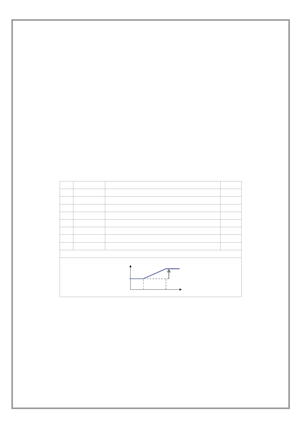
SET POINT CURVE IN COOLING
m
P 23
P 24
COMP.
MAX
= P22
COMP.
=0
SET POINT
 Loading...