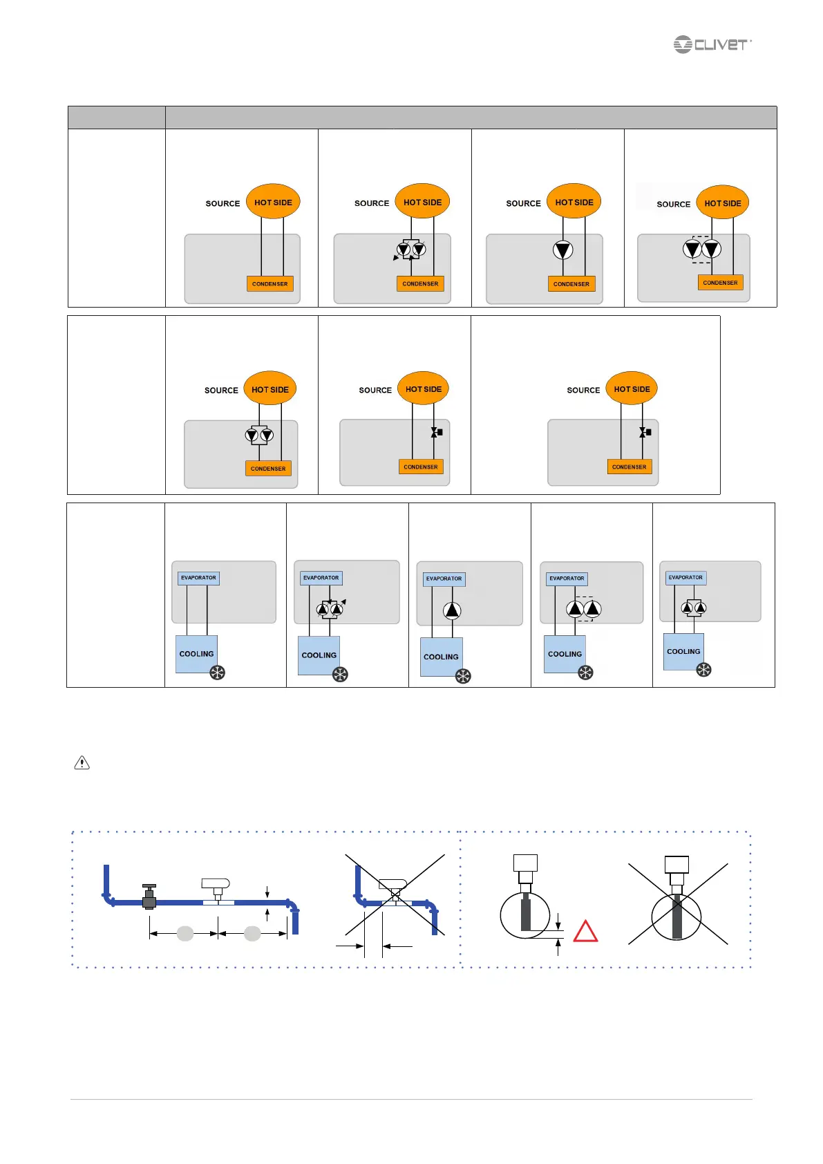
4.8 Hydronic unit diagrams - Cold only unit
4.9
Flow Switch
The ow switch must be present to ensure shutdown of the unit if water is not circulating.
It has to be installed in a duct rectilinear part, not in proximity of curves that cause turbulences.
Electrically connect the ow switch at the inlet arranged on the XC terminal block.
The ow switch must be set to the minimum reachable ow rate.
A. minimum distance
USER SIDE/
COLD
Standard
unit
(Std)
Unit
with VARYFLOW +
(VARYC)
Unit
with 1 ON/OFF pump
(HYGC1)
Unit
with 2 ON/OFF pumps
(HYGC2)
Unit
with Hydropack
(2PMC)
SOURCE SIDE/
HOT
Unit
with Hydropack
(2PMH)
Unit
with 2-way modulating valve
(VS2MH)
Unit with 2-way modulating valve
for high DP (V2MHP)
Functionalities Diagram hydronic assemblies - Cooling only unit
SOURCE SIDE/
HOT
Standard
unit (Std)
Unit
with VARYFLOW +
(VARYH)
Unit
with 1 ON/OFF pump
(HYGH1)
Unit
with 2 ON/OFF pumps
(HYGH2)
 Loading...