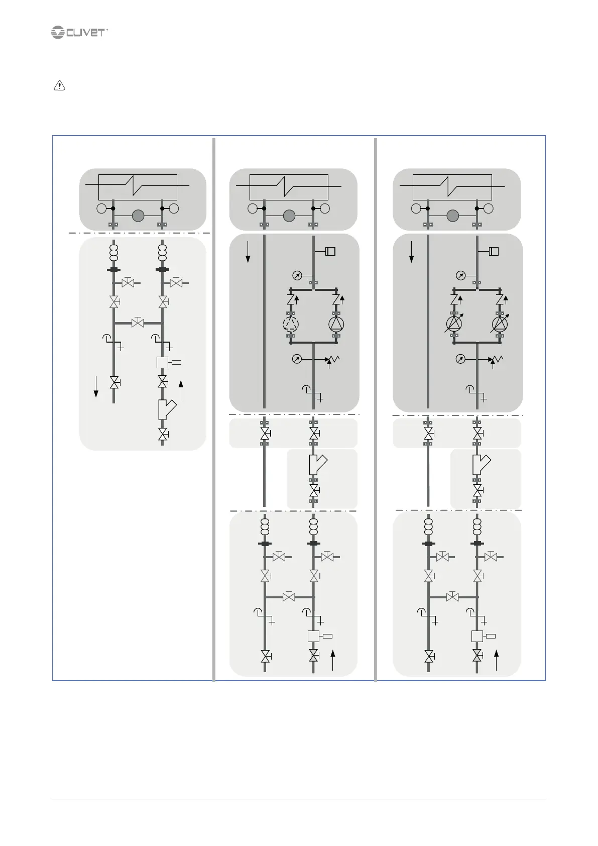
4.10 Recommended connection
The installer must dene:
•
component type
•
position in system
Examples:
PD
TT
PD
TT
F
UNITCUSTOMER
UNIT
1
F
6
7
12
8
OPTION
3
11
9
5
10
CUSTOMER
PD
TT
F
UNITCUSTOMER
13
14
15
16
18
19
17
OPTION
Standard unit Unit with 2 pumps Unit with VARIFLOW +
6
7
12
8
11
9
10
6
7
12
8
11
9
10
18
19
13
14
15
16
17
1
3
5
1
3
5
19
1 exchanger 11 drain
3 water temperature probe 12 Flow Switch
5 dierential pressure switch 13 System load safety pressure switch
6 antivibration joints 14 pressure gauge
7 piping support 15 non-return valve
8 exchanger chemical cleaning bypass 16 Pump
9 Cleaning system bypass 17 safety valve
10 vent 18 shut-o valve
19 lter
 Loading...