41
9 - TECHNICAL INFORMATION
Acoustic configuration: Standard (ST)/Extremely low noise(EN)
GENERAL TECHNICAL SPECIFICATIONS
ELECTRICAL DATA
Size
65D 70D 75D 80D 85D 90D 100D 110D 115D 120D 135E 150F 165F 180F
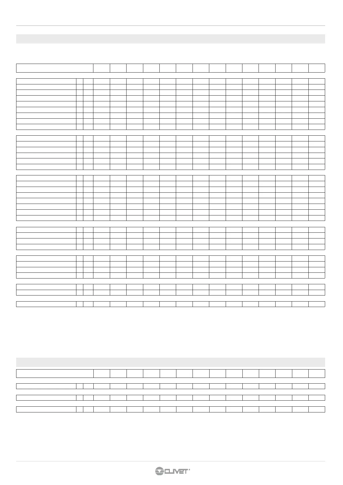
F.L.A. - FULL LOAD CURRENT AT MAX ADMISSIBLE CONDITIONS
F.L.A. - Total
A 132,4 141,7 153 164,3 170,9 177,5 196,3 218,9 225,5 232,1 270,2 308,3 328,1 347,9
F.L.I. FULL LOAD POWER INPUT AT MAX ADMISSIBLE CONDITION
F.L.I. - Total
kW 79,3 85,7 90,8 95,9 102,2 108,5 121,3 131,5 137,9 144,2 167,5 178,2 197,2 216,2
M.I.C. MAXIMUM INRUSH CURRENT
M.I.C. - Value
A 309,5 318 365 373,4 448 454,6 473,4 496 502,6 509,2 547,3 517 605,2 625
power supply: 400/3/50 Hz +/-6%
voltage unbalance: max 2 %
The F.L.A. data is to be considered in order to correctly size the supply line, whereas the M.I.C. data is used for the sizing of the protection device up the line.
Certain accessories and operations may entail a significant variation in the absorptions illustrated here. Contact our technical department
.
Size 65D 70D 75D 80D 85D 90D 100D 110D 115D 120D 135E 150F 165F 180F
COOLING
Cooling capacity 1 kW 195 207 223 234 251 286 312 334 353 371 406 440 497 560
Compressor power input 1 kW 41,2 44,2 47,3 50 53,4 59,5 65,1 70,2 75,4 79,3 86,1 93,7 106 119
Total power input 1 kW 41,5 44,5 47,6 50,3 53,7 59,8 65,4 70,5 75,7 79,6 86,6 94,2 106 120
Heating capacity total recovery 3 kW 224 237 257 269 289 327 356 383 407 428 466 506 574 646
Heating capacity partial recovery 3 kW 47 50 54 57 61 69 75 81 86 90 98 107 121 136
Cooling capacity (EN14511:2011) 2 kW 194 206 222 233 250 285 311 333 352 370 404 438 495 558
Total power input (EN14511:2011) 2 kW 43,3 46,5 49,8 52,5 55,5 62,1 67,5 72,8 78,3 82,5 89,9 97,8 110 126
EER (EN 14511:2011) 2 4,48 4,43 4,46 4,44 4,51 4,59 4,61 4,57 4,49 4,48 4,5 4,48 4,5 4,44
ESEER 2 6,11 6,15 5,87 6,03 5,88 6,02 5,99 6,15 6,09 6,07 6,1 6,28 6,21 6,24
HEATING
Heating capacity 4 kW 224 237 257 269 289 327 356 383 407 428 466 506 574 646
Compressor power input 4 kW 50,9 54,7 57,9 61,3 64,6 72,9 79,6 86,3 92,8 97,9 106 115 130 147
Total power input 4 kW 51,2 55 58,2 61,6 64,9 73,2 79,9 86,6 93,1 98,2 107 115 130 147
Heating capacity (EN14511:2011) 5 kW 224 237 257 269 289 327 356 383 407 428 466 506 574 646
Total power input (EN14511:2011) 5 kW 51,2 55 58,2 61,6 64,9 73,2 79,9 86,6 93,1 98,2 107 115 130 147
COP (EN 14511:2011) 5 4,38 4,31 4,42 4,37 4,45 4,47 4,46 4,42 4,37 4,36 4,36 4,4 4,42 4,39
COMPRESSOR
Type of compressors
SCROLL SCROLL SCROLL SCROLL SCROLL SCROLL SCROLL SCROLL SCROLL SCROLL SCROLL SCROLL SCROLL SCROLL
No. of compressors
Nr 4 4 4 4 4 4 4 4 4 4 5 6 6 6
Rated power (C1)
HP 30 35 35 40 40 45 50 55 55 60 60 75 75 90
Nominal Power (C2)
HP 35 35 40 40 45 45 50 55 60 60 75 75 90 90
Std Capacity control steps
Nr 4 4 4 4 4 4 4 4 4 4 5 6 6 6
Oil charge (C1)
l 7 8 8 10 10 9 10 10 12 11 11 20 20 17
Oil charge (C2)
l 8 8 10 10 9 9 10 12 11 11 20 20 17 17
Refrigerant circuits
Nr 2 2 2 2 2 2 2 2 2 2 2 2 2 2
INTERNAL EXCHANGER
Type of internal exchanger 6 PHE PHE PHE PHE PHE PHE PHE PHE PHE PHE PHE PHE PHE PHE
Water flow rate (Utility Side)
l/s 9,3 9,9 10,7 11,2 12 13,7 14,9 16 16,9 17,7 19,4 21 23,7 26,8
internal exchanger pressure drop
kPa 47 43 43 47 31 40 36 40 45 49 47 46 45 56
Water content
l 11 13 14 14 25 25 29 29 29 29 34 38 47 47
EXTERNAL EXCHANGER
Type of external exchanger 6 PHE PHE PHE PHE PHE PHE PHE PHE PHE PHE PHE PHE PHE PHE
Water flow rate (Source Side)
l/s 11,3 12 12,9 13,6 14,5 16,5 18 19,3 20,5 21,5 23,5 25,5 28,8 32,4
External exchanger pressure drop
kPa 46 51 52 51 32 40 33 37 36 39 46 49 52 65
Water content
l 14 14 16 18 29 29 38 38 43 43 43 47 56 56
CONNECTIONS
Water fittings 7 2" 1/2 2" 1/2 2" 1/2 2" 1/2 3" 3" 3" 3" 3" 3" 3" 3" 3" 3"
Water fittings 7 2" 1/2 2" 1/2 2" 1/2 2" 1/2 3" 3" 3" 3" 3" 3" 3" 3" 3" 3"
POWER SUPPLY
Standard power supply
V 400/3/50 400/3/50 400/3/50 400/3/50 400/3/50 400/3/50 400/3/50 400/3/50 400/3/50 400/3/50 400/3/50 400/3/50 400/3/50 400/3/50
(1) data referred to the following conditions : - internal exchanger water (evaporator) = 12 / 7 °C - external exchan-
ger water (condenser) = 30/35°C
(3) external exchanger water = 40/45°C
internal exchanger water = 12/7°C
(2) Data calculated according to EN 14511:2011 regulations referred to the following conditions :
(4) Data referred to unit in ‘OHI - Operation with reversal on the water circuit’ configuration
data referred to the following conditions : - internal exchanger water (evaporator) = 12/7 °C - external exchan-
ger water (condenser) = 40/45°C
The data do not consider the pump share, required to overcome the pressure drop for the solution circulation inside
the exchangers
(5) Data referred to unit in ‘OHI - Operation with reversal on the water circuit’ configuration
Data calculated according to EN 14511:2011 regulations referred to the following conditions :
- internal exchanger water (evaporator) = 12/7 °C
- external exchanger water (condenser) = 40/45°C
(6) PHE = plates
(7) internal exchanger inlet / outlet
 Loading...