Do you have a question about the Club Car 2005 FE290 and is the answer not in the manual?
| Brand | Club Car |
|---|---|
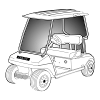
| Model | 2005 FE290 |
| Category | Offroad Vehicle |
| Language | English |
General safety statements to be heeded during operation, repair, or service.
Schedules for periodic service, lubrication, engine oil, fueling, and battery maintenance.
Guide to identify operating difficulties, probable causes, and refer to relevant sections for checks.
Description of the vehicle's 12-volt DC electrical system and its circuits.
List of test procedures for diagnosing electrical issues, including specific component tests.
Component responsible for starting the engine and generating electrical power.
Component that regulates vehicle voltage.
Component for controlling vehicle power.
Component used in the electrical system to engage the starter motor.
Component that protects electrical circuits from overcurrent.
Switch activated by the accelerator pedal position.
Switch used to stop the engine under certain conditions.
Switch that prevents starting the engine unless the transmission is in neutral.
Mechanical component related to the neutral lockout system.
Audible warning device activated when the vehicle is in reverse.
Switch that activates the reverse warning buzzer.
Indicator light for low engine oil level.
Instrument displaying fuel level and engine operating hours.
Component in the fuel tank that measures fuel level.
Device that prevents the engine from exceeding a set RPM.
Component that provides high voltage for the spark plug.
Sensor that detects the engine oil level.
Information about the vehicle's battery.
Information regarding ground cables.
Overview of the 4-cycle, overhead valve, single-cylinder engine.
Information on spark plug selection, gap setting, removal, and installation.
Information on cylinder head compression and breather valve function.
Procedure for removing the engine and its crankcase cover.
Procedures for installing the oil level sensor and crankcase cover.
Procedures for removing and installing ignition coil and flywheel.
Steps for engine installation, torque specs, and adjustments.
Information and procedures for carburetor maintenance, including main jet changes.
System connecting throttle, governor, and pedals to the engine for proper operation.
System for managing air intake and cold engine starting.
Procedures for replacing the air filter element.
Procedures for removing and installing fuel filters.
Procedures for fuel pump removal, disassembly, cleaning, and installation.
Procedures for fuel tank removal, disposal, storage, and installation.
Guidelines for routing and maintaining fuel lines.
Information on the fuel shut-off valve operation and positions.
Component that reduces exhaust noise.
Procedure to remove the muffler.
Procedure to install the muffler.
Overview of the heavy-duty, fully-synchronized unitized transaxles.
Components for gear selection and neutral safety feature.
Transaxle governor system and lubricant level maintenance.
Procedures for removing and installing axle shafts and bearings.
Procedures for removing and installing the complete unitized transaxle.
Procedures for removing, installing, and adjusting the shifter cable.
Overview of the torque converter system and guidance for troubleshooting issues.
Procedures for inspecting, removing, and installing the drive belt.
Procedures for removing, cleaning, inspecting, disassembling, assembling, and installing the drive clutch.
Procedures for removing, disassembling, inspecting, assembling, and installing the driven clutch.