Do you have a question about the Club Car Precedent 2004 and is the answer not in the manual?
General safety statements to be heeded during operation, repair, or servicing.
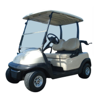
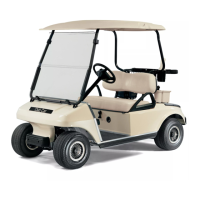
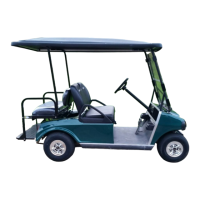
Detailed specifications for two and four-passenger electric vehicles.
Procedure for identifying the vehicle's serial number using the decal.
Recommendations for appointing a safety committee for golf car operations.
Guidelines and warnings for storing the electric vehicle for extended periods.
General safety statements to be heeded during operation, repair, or servicing.
Detailed specifications for two and four-passenger electric vehicles.
Procedure for identifying the vehicle's serial number using the decal.
Guidelines and warnings for storing the electric vehicle for extended periods.
Procedure for returning a stored electric vehicle back into service.
Instructions and precautions for cleaning the vehicle's body panels and seats.
Guidelines for cleaning the vehicle seats based on the level of soiling.
Procedures for repairing minor damage, scratches, and abrasions on the body.
Step-by-step instructions for removing the front body components.
Step-by-step instructions for installing the front body components.
Procedure for removing the floor mat retainers from the vehicle.
Procedure for installing the floor mat retainers onto the vehicle.
Steps for removing the kick plate and charger bezel assembly.
Steps for installing the kick plate and charger bezel assembly.
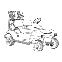
Information on mounting various accessories using the Structural Accessory Module (SAM).
Procedure for removing the Structural Accessory Module (SAM).
Procedure for installing the Structural Accessory Module (SAM).
Steps for removing the bag rack and related components.
Steps for installing the bag rack.
Procedure for removing the rear beauty panel.
Procedure for installing the rear beauty panel.
Securing the access panel to the rear underbody.
Instructions for removing the rear underbody from the vehicle.
Step-by-step instructions for removing the dash assembly.
Step-by-step instructions for installing the dash assembly.
General information and safety warnings related to the pedal group.
Procedure for removing the pedal group assembly from the vehicle.
Description of the self-adjusting, mechanically-expanding shoe drum brakes.
Step-by-step procedure for removing brake shoes.
Using pliers to remove the shoe retainer clip and pin.
Grasping and removing brake shoes and springs from the assembly.
Removing the adjuster wheel and washers from the backing plate.
Steps for removing the brake cluster assembly from the transaxle.
Steps for installing the brake cluster assembly onto the transaxle.
Procedure for disconnecting and removing brake cables.
Procedure for connecting and installing brake cables.
Overview of the rack and pinion steering system.
Safety warnings and procedures for steering wheel removal and installation.
Step-by-step instructions for removing the steering wheel.
Step-by-step instructions for installing the steering wheel.
Procedure for removing the steering column assembly.
Procedure for installing the steering column assembly.
Steps for removing the rack and pinion assembly from the vehicle.
Procedure for removing the dust seal from the rack and pinion.
Removing snap rings from the pinion assembly.
Procedure for removing the pinion from the rack and pinion housing.
Lubrication points and procedure for the front suspension components.
Information on wheel alignment, limited to camber and toe-in adjustment.
Procedure for checking and adjusting the camber angle of the front wheels.
General information on front suspension components.
Steps for removing the tie rod ends from the steering gear.
Steps for installing the tie rod ends onto the steering gear.
Procedure to inspect for play in the front wheel hub assembly.
Steps for removing the front wheel hub assembly.
Importance of proper wheel and tire care for vehicle handling and lifespan.
Safety warnings for wheel removal and installation procedures.
Step-by-step procedure for removing a wheel from the vehicle.
Step-by-step procedure for installing a wheel onto the vehicle.
Safety warnings regarding tire selection and handling.
Description of the independent rear suspension with leaf springs and shocks.
Safety warnings and inspection for shock absorbers.
Procedure for removing and inspecting the rear shock absorbers.
Procedure for installing the rear shock absorbers.
Safety warnings for leaf spring removal and installation.
Procedure for removing the rear leaf springs.
Importance of preventive maintenance for vehicle performance and longevity.
Daily checklist for ensuring proper working condition and safety.
Daily checklist for inspecting vehicle operation and performance.
Overview of the 48-volt IQ System electrical system and its components.
Description of the shunt-wound motor and speed controller function.
Explanation of motor braking functions: Zero Speed Detect, Pedal Down, Pedal Up.
Function preventing uncontrolled rolling on slopes without park brake.
Components and sub-circuits of the main control circuit.
Functions performed by the onboard computer (OBC) circuit.
The speed control circuit's function in activating the solenoid.
Using the IQDM handset for troubleshooting vehicle issues.
Guide for identifying symptoms, causes, and corrective actions using IQDM.
Procedure to check battery voltage using a multimeter without IQDM.
Testing MCOR voltage using the IQDM handset for accelerator pedal position.
Testing MCOR voltage using a multimeter without IQDM.
Testing voltage at the A1 and A2 motor terminals.
Testing the Tow/Run switch using the IQDM handset.
Testing the Tow/Run switch using a multimeter.
Testing key switch and MCOR limit switch with IQDM handset.
Testing key switch and MCOR limit switch with multimeter.
Testing MCOR potentiometer connections to the speed controller.
Testing the solenoid lockout circuit connection at pin 5.
Testing the motor speed sensor using the IQDM handset.
Testing the motor speed sensor using a multimeter.
Testing the Forward/Reverse switch using the IQDM handset.
Testing the Forward/Reverse switch using a multimeter.
Safety warnings and testing procedures for the key switch.
Step-by-step instructions for removing the vehicle's key switch.
Step-by-step instructions for installing the vehicle's key switch.
Procedure for removing the battery warning light assembly.
Procedure for installing the battery warning light assembly.
Procedure for removing the Forward/Reverse rocker switch.
Procedure for installing the Forward/Reverse rocker switch.
Procedure for removing the electronics module cover.
Procedure for installing the electronics module cover.
Procedure for removing the Tow/Run switch.
Procedure for installing the Tow/Run switch.
Procedure for removing the Motor Controller Output Regulator (MCOR).
Procedure for removing the reverse buzzer.
Procedure for installing the reverse buzzer.
Procedure for removing the electronics module assembly.
Procedure for removing the solid state speed controller.
Procedure for installing the solid state speed controller.
Procedure for removing the solenoid.
Procedure for removing the onboard computer (OBC).
Procedure for installing the onboard computer (OBC).
Inspection of the charger receptacle for wear and damage.
Procedure for removing the charger receptacle.
Procedure for installing the charger receptacle.
Explanation of deep-cycle batteries and their components.
Chart addressing common misconceptions about deep-cycle battery care.
Safety warnings and procedure for replacing vehicle batteries.
Preventive maintenance steps to keep batteries in sound operating condition.
Regular steps for maintaining battery health and preventing corrosion.
Easiest method to monitor battery condition by observing charger ammeter.
Procedure to check battery set and individual battery voltages after charging.
Measuring the specific gravity of battery electrolyte for state of charge.
Step-by-step instructions for performing the hydrometer test.
How to correct hydrometer readings for temperature variations.
Table correlating specific gravity readings to approximate battery state of charge.
Procedure for conducting a discharge test to simulate vehicle operating conditions.
Table for interpreting discharge test results based on battery voltage and time.
Description of the 48-volt DC shunt-wound traction motor.
Tests performed on the motor without disassembly using a multimeter.
Procedure to test for internal short circuits in the motor.
Detailed inspection points for armature abnormalities and commutator condition.
Procedure to test the armature for ground faults.
Inspection of field windings for signs of overheating or damage.
Procedure for removing the motor speed sensor.
Procedure for installing the motor speed sensor.
How to identify Type G transaxles by gear case bolt head orientation.
Lubrication points and procedure for the Type G transaxle.
General information on axle bearings and shafts for Type G transaxle.
Procedure for removing the axle shaft and its oil seal.
Procedure for installing a new axle shaft oil seal and adapter ring.
Procedure for installing the rear axle onto the transaxle housing.
Step-by-step instructions for removing the transaxle from the vehicle.
Procedure for disassembling, inspecting, and reassembling the transaxle.
How to identify Type K transaxles by gear case bolt head orientation.
Lubrication points and procedure for the Type K transaxle.
General information on axle bearings and shafts for Type K transaxle.
Procedure for removing the axle shaft and its oil seal for Type K.
Procedure for installing axle shaft and oil seal for Type K transaxle.
Procedure for removing axle bearings and collars.
Procedure for installing axle bearings and collars.
Step-by-step instructions for removing the Type K transaxle.
Procedure for disassembling, inspecting, and reassembling the Type K transaxle.
| Brand | Club Car |
|---|---|
| Model | Precedent 2004 |
| Category | Offroad Vehicle |
| Language | English |