CMT2380F17
Rev0.1 | 136/347
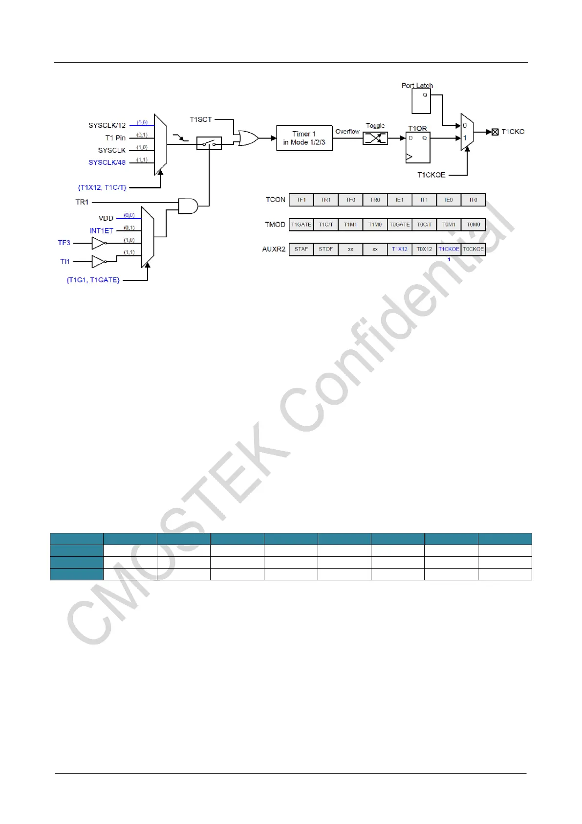
Figure 16-11. Timer 1 in Clock Output Mode
How to Program Timer 0/1 in Clock-out Mode
• Select Timer 0/1 clock source.
• Determine the 8-bit reload value from the formula and enter it in the TH0/TH1 register.
• Enter the same reload value as the initial value in the TL0/TL1 register.
• Set T0CKOE/T1CKOE bit in AUXR2 register.
• Set TR0/TR1 bit in TCON register to start the Timer 0/1.
In the Clock-Out mode, Timer 0/1 rollovers will not generate an interrupt This is similar to when Timer 1 is
used as a baud-rate generator. It is possible to use Timer 1 as a baud rate generator and a clock generator
simultaneously. Note, however, that the baud-rate and the clock-out frequency depend on the same overflow
rate of Timer 1. So, software usually disables the Timer 0/1 interrupt in this kind of application.
16.1.6 Timer 0/1 Register
TCON:Timer/Counter Control Register
SFR Page = 0~F
SFR Address = 0x88
Bit 7: TF1, Timer 1 overflow flag.
0: Cleared by hardware when the processor vectors to the interrupt routine, or cleared by software. 1: Set
by hardware on Timer/Counter 1 overflow, or set by software.
Bit 6: TR1, Timer 1 Run control bit. 0: Disabled to stop Timer/Counter 1.
1: Enabled to start Timer/Counter 1.
Bit 5: TF0, Timer 0 overflow flag.
0: Cleared by hardware when the processor vectors to the interrupt routine, or cleared by software. 1: Set
by hardware on Timer/Counter 0 overflow, or set by software.
Bit 4: TR0, Timer 0 Run control bit. 0: Disabled to stop Timer/Counter 0.
1: Enabled to start Timer/Counter 0.
TMOD:Timer/Counter Mode Control Register



 To Next Page