7
1. REQUIRED FOR INSTALLATION
Your Powerclean Salt Econ Chlorinator includes the following:
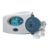
1 Control Center
1 Econ Style Cell Housing
1 O-Ring
1 Jumper Wire
1 Electrolytic Cell with Cord and Cap
1 Mounting Bracket
1 Cleaning Tool
1 Owner’s Manual
The following items will also be required to install the Powerclean Salt Econ system:
Screwdriver
Level
Hacksaw or PVC Cutter
Wire Stripping Tool
Electric Drill
8AWG Copper Bonding Wire
Mounting Screws
INSTALLING THE CONTROL CENTER WARNING! When using electrical products, basic precautions should always be followed:
be sure to read and follow safety instructions on pages 3 though 5.
DANGER
Risk of electric shock, which can result in serious injury or death. Before attempting installation or
service, make sure that all power to the circuit supplying power to the system is disconnected/
turned o at the circuit breaker. Connect only to a circuit protected by a ground fault circuit-
interrupter (GFCI).
2. INSTALLATION LOCATION
a. It is recommended to install the salt cell installed as the last piece of pool equipment in line, on the return to the pool,
after the heater. (See illustration 1 on next page)
b. Installing horizontally will ensure the ow sensor remains submerged.
c. If installed vertically, the cell cap must be on top.
d. Always use a check valve before the cell to prevent chlorine backow.
e. All ttings are 2 inch Socket.
f. NONE: Do not install on pools using a stainless steel liner or stainless steel plumbing.
BELOW GRADE INSTALLATION:
g. This exists when the water level of the pool is above the height of the pool equipment.
h. The system should be wired to the load side of the time clock to power on ONLY when the primary pump is operating.
i. If valves are not present to isolate the equipment, one ball valve should be installed on the inlet side of the cell. This
allows the cell to be removed for cleaning when necessary.
j. A one-way check valve should be installed on the outlet side of the cell. This will eliminate the possibility of having a gas
build-up (which could cause possible cell damage.)
k. CAUTION: Failure to follow proper below grade installation procedures may lead to damage to pool equipment.
C. INSTALLATION PROCEDURE