Zero-3 / 5-Channel Motor Controller
CNC-STEP e.K. ▪ Siemensstrasse 13-15 ▪ 47608 Geldern ▪ Germany
Support: +49 (0)2831/91021-50
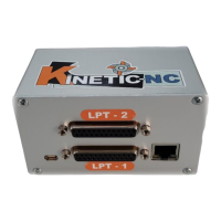
4.3.5 LPT ports
The connection with the controller PC is by means of a 25-pin D-sub connector (LPT = parallel
port) on the rear panel. Most signals for basic functions (phase/direction, spindle on/off, etc.) are
available on the left connector. The plug-in connector on the controller is male, i.e. to connect it
with the PC a 1:1 extension cable with a male/female plug is required.
The pins ( LPT1) are assigned as follows:
Relay 2 (cooling/suction)
Ref. switch 4. Axis or tool
probe
Watchdog (toggle/charge
pump)
Reference switches X1 and
X2