SHENZHEN CNCOTE TECHNOLOGY CO., LTD
Website: www.cncote.com Attn: Jack Foo,
Skype, cncote01, whatsapp, 008613480148499, email, jackfoo168@gmail.com
7.2, Notice of Installation:
To prevent theft of the Device, the device should be installed as covertly as possible.
Notice as following:
7.2.1, Avoid placing the Device close to higher power electrical devices, such as reversing
radar, anti-theft device or other vehicle communication equipment.
7.2.2, The Device should be fixed into position with cable ties or wide double-side tape.
7.2.3, Device has built-in GSM antenna and GPS antenna. During installation, please
make sure the receiving side face is up, with no metal object above the device to interfere
with GPS reception.
7.2.4, For safety , do NOT remove the fuse of device cable.
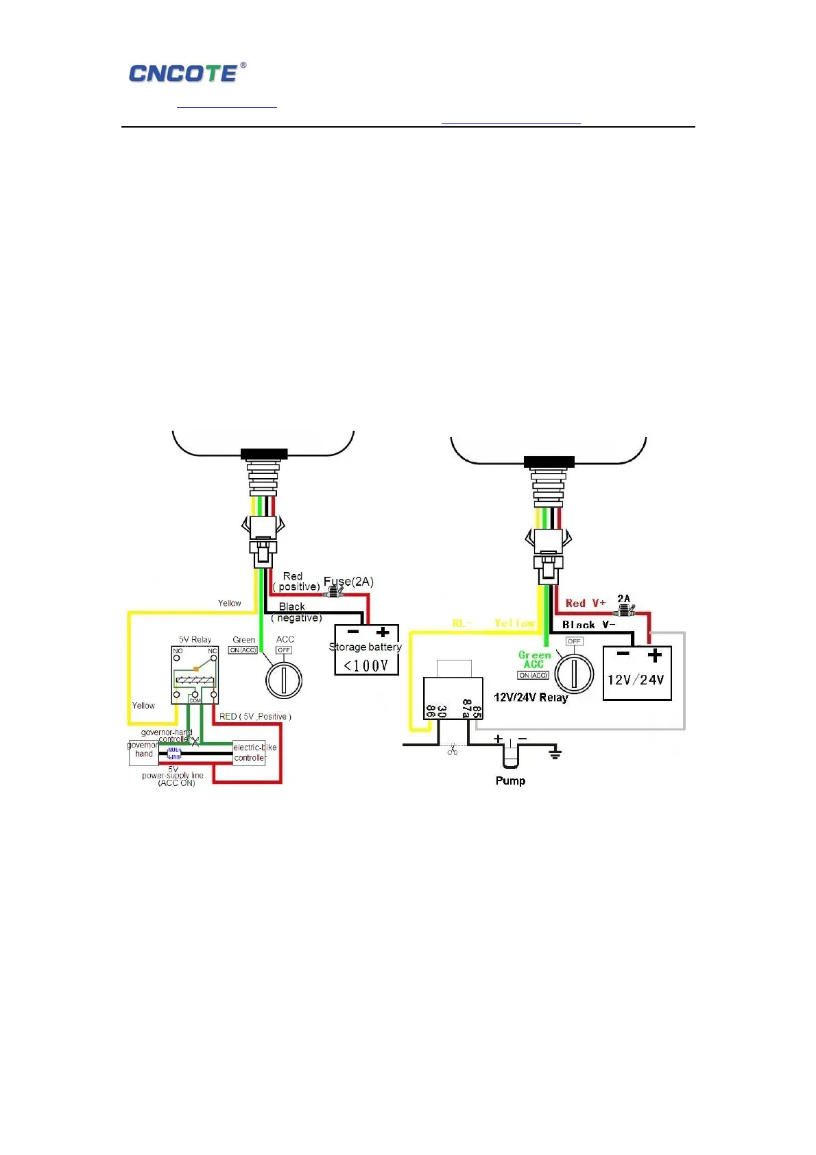
7.3, Device wiring diagram:
For Motorbike and E-motorbike For car & vehicle & trucks
7.4, Steps of installation:
7.4.1, Open the back cover ,insert a SIM card to SIM card slot .
7.4.2, Switch power button up(power on) .
7.4.3, Connect the power code with the interface of device. Now three LED lights will
lighting .Make sure the receiving side face up,without any metal object shelter.
The LED lights will flashing after 1 to 5mins. It shows working normally.
7.4.4, Close the back cover.
7.4.5, Please ask professional technical to connect wires and install to the vehicle. After
correct installation, the RED led will flashing, 1 min. Later the BLUE led will flashing too.
 Loading...