1
7
8
9
10
11
1
17
1
1
1 1
18
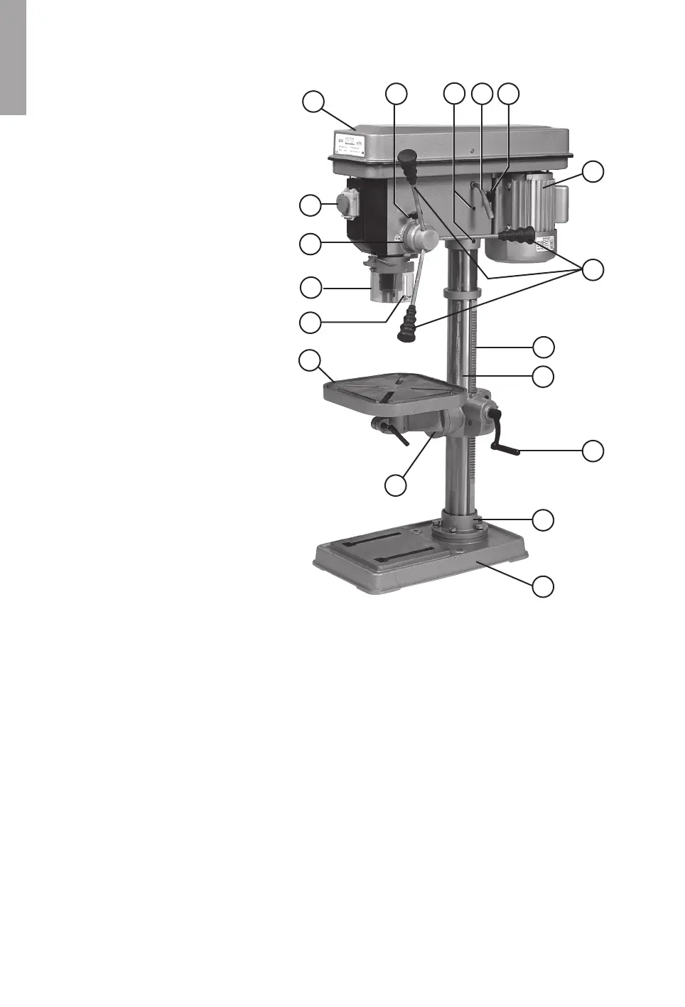
Product Description
1. On/off switch
2. Depth guage
3. Guard
4. Motor
5. Feed handle
6. Tableheightadjusterwheel
7. Belt housing
8. Pillar
9. Rack
10. Pillar support
11. Base plate
12. Socket set screw x2
13. Wing nut
14. Lever
15. Wing nut
16. Chuck key
17. Table
18. Table support
Assembly
1. Positionthebasefootplate(11)ontheoor.
2. Attach the Pillar support (10) to the base using the nuts and bolts.
3. Attach the table support (18) and the table (17) together with the gear rack (9) and pillar (8).
Tightenthelockingscrewonthebackofthetablesupport,thislocksthetableatthedesired
height.
4. Youcannowmountthemainbody,lockingitinplacewiththetwosocketheadcapscrews
(12).
5. Becausethemachineislubricatedatthefactory,werecommendthatyourstrunitfor
about 15 minutes at low speed.
NOTE! The taper (MT2-B16) and insides of the spindle and chuck need to be de-greased in
ordertottightly.Hitthetaperandchuckwithawoodenmallet.
Mounting on the floor
Beforeusingthemachineitmustbeanchoredtotheoororotherxedsurface.Thebase(11)
has therefore been pre-bored allowing it to be bolted down.
 Loading...