Do you have a question about the Coastal Amusements SPIDER-BOT and is the answer not in the manual?
Configure coin input for Coin 1, setting credit ratios.
Configure coin input for Coin 2, setting credit ratios.
Set ticket payout based on coins inserted.
Adjust game difficulty levels.
How bonus tickets are awarded based on hit numbers.
How tickets are awarded in flat pay mode.
Steps to reset the game system.
Troubleshooting for gantry not homing on power up.
Troubleshooting for right-stop switch failure.
Troubleshooting for lower-stop switch failure.
Identifies fuses F1, F2, F3, and F4 on the main board.
How to test displays, LEDs, and bulbs.
Testing various input signals and switches.
Procedures for testing gantry movement and claw operation.
Testing ticket dispenser, I/R receiver, meters.
How to perform and interpret the sound test.
Pin configuration for main board connectors.
Pin configuration for external connectors.
Pin assignments for power supply and input switches.
Pin assignments for inter-board connections.
Circuit diagrams for I/R boards.
Pin configuration for the matrix display board.
| Manufacturer | Coastal Amusements |
|---|---|
| Category | Arcade Game Machines |
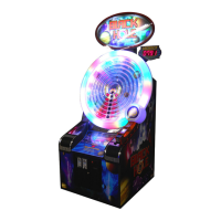
| Game Title | SPIDER-BOT |
| Players | 1 |
| Age | All Ages |
| Tickets | Yes |
| Skill Based | Yes |
| Type | Redemption |
| Display | LCD |
| Control | Joystick |
| Power Supply | 110V |