98-148231-A
www.cobham.com/satcom
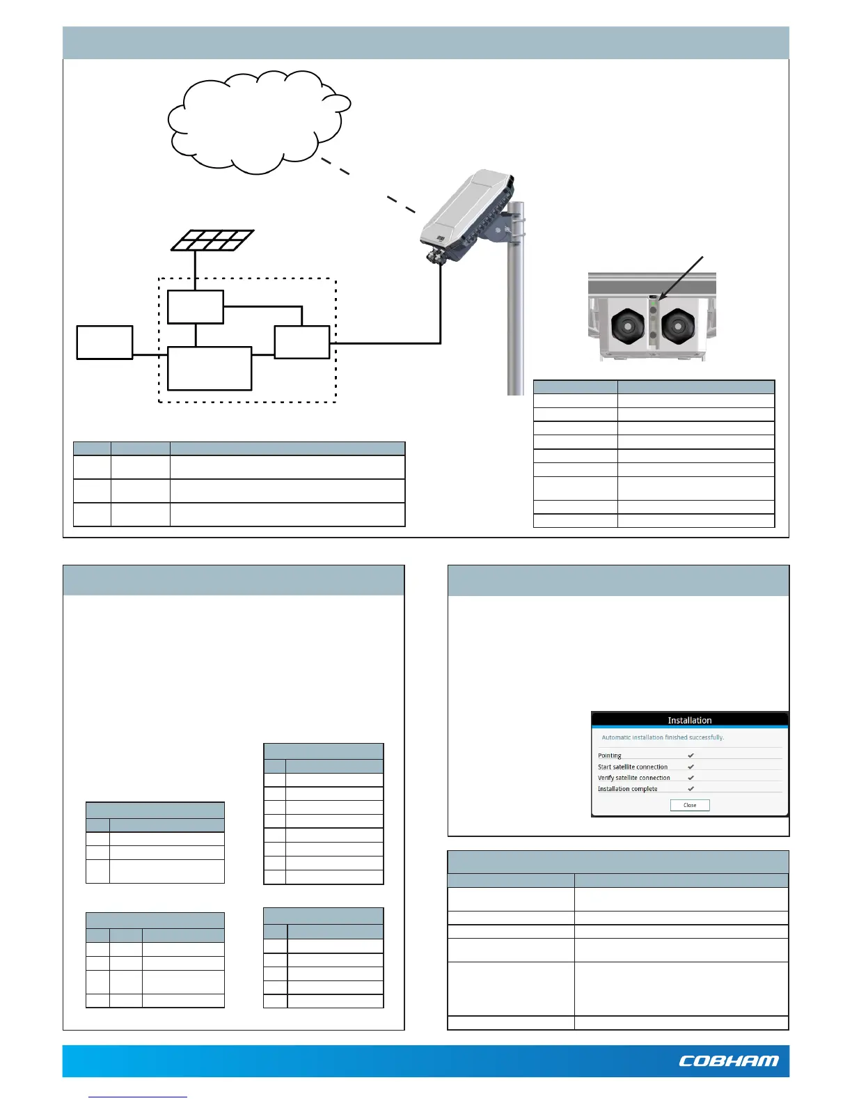
System Conguration - Example
Technical specications
Item Specication
Dimensions 202x202x51.8mm
8.0x8.0x2.0inches
Weight 1.6kg/3.5lbs(excl.cellularmodem)
Operatingtemperature -40to75°C
PowersupplyPoE
PowersupplyDC
Accordingto:PoE+IEEE802.3attype2class4
10.5to32VDC
Powerconsumption Powersave(Wake oncongured):110mW
Sleepmode:2.5W
Max.powerwhentransmitting:
• PoE:24W
• DC:21W
IP grade IP66
Number Cable Requirements
1 DCPowercable 1.5 mm
2
,UVresistant,Temperature:-40to+75deg.C,Maxcable
length:12metersat12Voperation,200metersat24Voperation
2 LAN cable Cable:EthernetMin.Cat5Solidcopperwire,STP.Max.length:100m
PoE source according to PoE+ IEEE 802.3at type 2 class 4
3 I/O cables 0,2mm
2
to 0,5 mm
2
(26AWGtil20AWG),outputupto2A.
Useshieldedcableoninputifnotactivelydrivenhigh/low.
If the LEDturnssteady yellow,itmeanstheinstallationfailed,e.g.becau-
setheterminalwasunabletodetectastableBGANsignalorveriifythe
networkconnection.
Ifyouconnectacomputerlocallytotheterminal,youcanusethebuilt-in
webinterfacetofollowtheprogressonscreenduringinstallation,andtosee
warningmessagesincasetheinstallationfailed.
1. ConnectyourcomputertotheLANinterfaceoftheEXPLORER540.
2. Openyourbrowseronthe
connectedcomputer.
3. Poweruptheterminal.
4. Accessthewebinterface
at the local IP address
(default192.168.0.1).
5. Entertheusername:User
andpassword:<serialnum-
beroftheterminal>.
Verifying and troubleshooting the installation
LED status Description
Off LightindicatorhasbeendisabledorPoweroff
Greenashingrapidly Startingup
Yellowashing BGANpointing
Greenashing Verifyingnetworkconnectivity
Green constant Ready
Yellowashingrapidly Closingdown
Yellowconstant Warning(userrecoverable).
Seewebinterfaceforthewarningtext.
Red constant Error.Seethewebinterface.
Blueashing Uploadingsoftwaretotheterminal
LAN/PoE connector (X1 or X2)
Pin Signal
1 TXp
2 TXm
3 RXp
4 POE+
5 POE+
6 RXm
7 POE-
8 POE-
DC power connector (X4)
Pin Signal
1 DCIN+
2 DCIN-
3 GND(optional-forconnection
ofshield)
Connectors and pin allocation
USB connector (X6)
Pin Signal
1 +5V
2 Dm
3 Dp
4 ID
5 GND
I/O connector (X5)
Pin Signal Details
1 GPI Requestwakeupinput
2 GPO Terminalreadyoutput
3 GPIO M2Mremotecontrol/
status,input/output
4 GND Ground
IMPORTANT:Youmustuseeither X1 orX2forLAN,notboth!
TheEXPLORER540hasthefollowingconnectors/terminals:
• X1: LAN/PoE, Spring-loaded terminals
• X2:LAN/PoE,RJ-45connector
• X3:SIMcard
• X4:DCinput,Screwterminals
• X5: I/O, Spring-loaded terminals
• X6:USB,microBconnector
• X7:ChassisGND,Screwterminal
Battery
M2Mindoor
equipment
Indoorequipment
PoE
injector
Probe
Solar panel
EthernetwithPoE
Internet
BGANM2Mservicevia
satellite
Light indicator
(LED)
Note:TheLEDisdisabled after completion
of the installation process.
Note:Thisdrawingisjustanexample.Yourcongurationmayuseothertypesofequipment.
 Loading...