28557
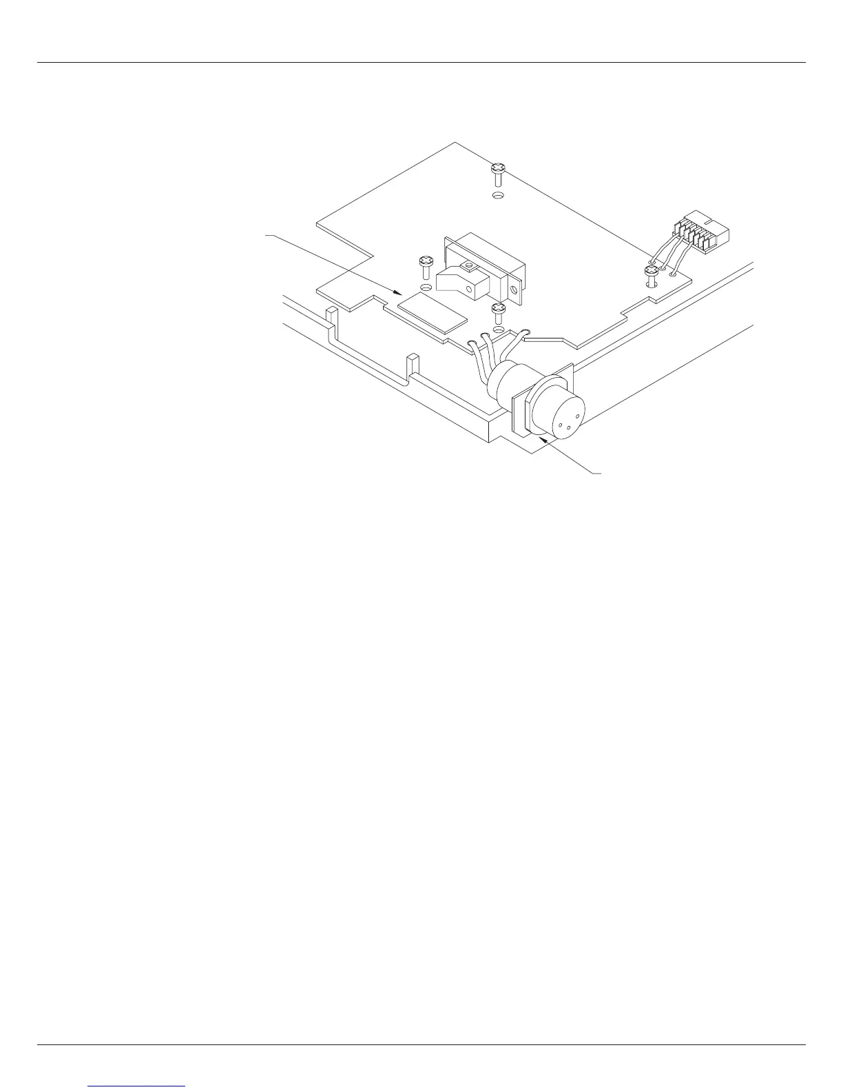
Note: Remove the
" 220V ~ " label
The ON-OFF Switch is placed
in the printer panel cutout and
fixed to the PCB with a glue pad
DC power supply circuit board is fixed
to the mounting frame with four screws
2.3.1 Mounting of the DC power supply
Placethegroundconnectionoverthereartransformerhole,andxitwiththeground
screw.
Placethemountingframewherethetransformerwasmounted,andxitwiththetwo
screws from the transformer.
ThenplacetheDCpowersupplymoduleonthemountingframe,andxitwithfour
screws.
Be sure the power ON-OFF switch is correctly placed in the panel cut out slot.
Press the plate with the DC input connector in to the panel cut out the formen AC
cord receptable.
Connect the output cable to the printer Main Control Board.
2.3.2Modicationoftheprintermaincontrolboard
If the printer is equipt with a DC power supply module of other type than from ECI, it
is necessary to modify the printer main board. As seen below, the diode D28 (D10) on
the printer main board is short circuited.
If the printer is equipt with a DC power supply module from ECI, module no. 628471 it
is not recommended to short circuit the diode D28 (D10) on the printer main board.
0627
 Loading...