4Co n n e ct the red lead of DC power co rd to an
a c ce s s o ry 12 volt fuse.
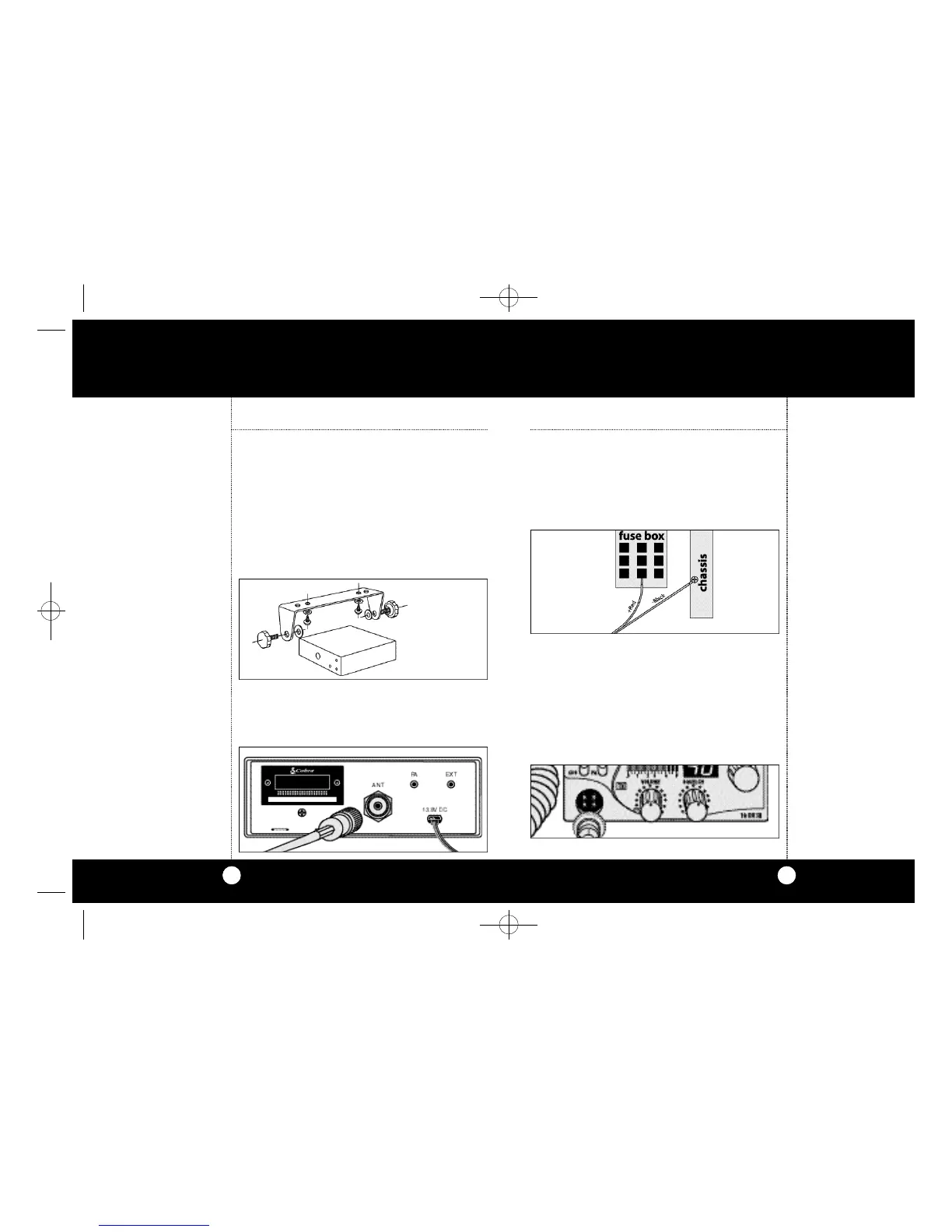
5Co n n e ct the black lead to the negat i ve side of
the auto m o b i l e.This is usually the chassis.Any
co nve n i e nt location with good elect ri cal co nt a ct
( re m ove paint) may be used.
6Mo u nt the microphone bra c ket on ri g ht side of
the tra n s ce i ver or near it using two scre w s sup-
p l i e d.When mounting in an auto m o b i l e,p l a ce
the bra c ket under the dash so the micro p h o n e
is readily acce s s i b l e.
7Attach the 4-pin microphone cable to recepta-
cle on front of unit and install unit in bracket
securely.
Mo u nting and Co n n e ct i o n s
Se l e ct a location for the tra n s ce i ver and micro-
phone bra c ket that is co n ve n i e nt for ope rat i o n .
In auto m o b i l e s ,the tra n s ce i v er is usually mounte d
to the undern e a th of the dash panel,with the
m i c rophone bra c ket beside it.
1Hold the radio with mounting bra c k et in the
ex a ct location desire d.Re m ove the mount i n g
b ra c ket and use it as a te m p l ate to mark the
l ocation for the mounting scre ws.
2Drill nece s s a ry holes and secure mount i n g
b ra c ket in locat i o n .
3Co n n e ct the antenna cable plug to the re ce p t a-
cle marked “A N T”on the back of the unit.
3
Mounting and
Connections
Note
Before installing the CB radio,
visually check the vehicle bat-
tery connections to determine
which battery terminal, posi-
tive or negative (positive is the
larger of the two) is grounded
to the engine block
(or chassis).
O p e r a t i o n
2
Mounting and
Connections
Note
The transceiver is held in the
universal mounting bracket by
two thumb screws, permitting
adjustment at the most conve-
nient angle.
A universal mounting bracket
is supplied along with self tap-
ping screws and star washers.
To mount the transceiver:
O p e r a t i o nInstallation Installation
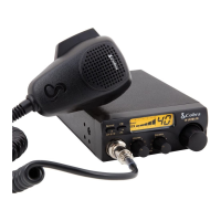
CB Transceiver
19 DX III. LAYOUT(4478) 8/9/00 4:35 PM Page 2
 Loading...