The Cobra 4625-4627 CAN/PLIP is an automotive anti-theft system designed for 12V battery vehicles with a negative pole connected to the vehicle body. It can be installed and configured as either a CAN (Controller Area Network) or PLIP (Programmable Logic Input/Output) system. In CAN mode, the unit reads data directly from the vehicle's CAN network. In PLIP mode, it connects to central door locking motors, door locking switches, and/or direction lights. The system can be armed/disarmed using the vehicle's original remote control, a Cobra remote, or an optional Driver Card.
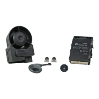
Key Components:
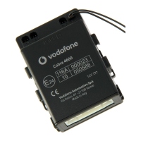
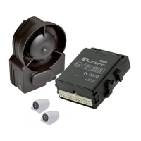
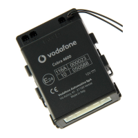
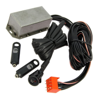
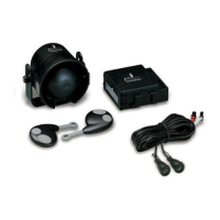
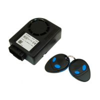
- Main alarm unit
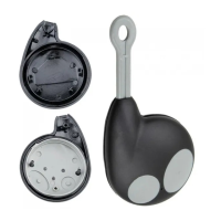
- Wireless back-up battery siren or wired siren/loudspeaker
- Main unit universal wiring harness
- Siren wiring harness
- Siren bracket
- Ultrasonic sensors
- Installation accessories
- LED / control button
- Quick reference user manual
- Pin Code card
Installation Methodology:
Installation requires accessing vehicle-specific technical documents, the Data Linker tool, and Antares software from the www.cobra-at.com installer area. The Data Linker programming tool, consisting of a USB interface module, a 12V DC power supply, and Antares software, is used to customize the product for the specific vehicle. Antares allows configuring and programming the CAN/PLIP software. Users must select the vehicle type (Auto - Car), product type (Antifurti auto - Car alarms), brand (e.g., Volkswagen), and model (e.g., Polo) to define the installation solution. It is recommended to check for CAN application availability first, as it offers the best compromise between functionalities and fitting time. If no CAN application is available, the PLIP alarm range (AK4600 - 4400 Plip) should be considered. If neither is available, generic "Application manuals" for the 4600 range in PLIP configuration can be used.
System Configuration (using Antares software):
- Connect all Data Linker components and power the system.
- Run Antares. The software automatically checks for updates if connected to the internet. Always download the latest update.
- Select the language.
- Select "alarm and modules."
- Select product "4600" as "1 wire" or "2 wire."
- Select the procedure "firmware update."
- Click "proceed."
- Select the vehicle brand, model, and model year.
- Click "proceed."
- Confirm and continue.
- Wait for the programming confirmation window.
PIN Code Card Preparation:
The separate PIN Code label from the back of the main unit must be removed and placed onto the supplied PIN Code Card for safekeeping.
Installation Procedure:
Components should be placed in secure, difficult-to-access locations to maximize protection. Avoid interference with moving parts.
- Alarm unit: Fit inside the vehicle, away from heat sources, with the main connector oriented downwards.
- Siren: Install in the engine bay or inside the vehicle, away from heat sources, with the main connector oriented downwards.
- Ultrasonic volumetric sensor: Transducers should be fixed to the top of the A-pillars, pointed towards the rear window, or to the top of the C-pillars, pointed towards the windscreen, as parallel as possible to the side windows.
- Emergency LED/control button: Fit on the dashboard in a visible position, easily accessible by the driver.
- Bonnet pushbutton: Required if the vehicle lacks an original one. Refer to the vehicle-specific CAN/PLIP installation sheet.
- Antennas (main unit and siren): Crucial for proper system performance. Do not cut, wrap, connect to other cables or the vehicle body, and keep separate from the main wiring harness and metallic parts.
Electrical Connections:
- WARNING: Disconnect the battery negative cable before installation to prevent damage to the vehicle's electrical system. Reconnect only after installation. If not disconnected, exercise caution to avoid errors from original central units.
- Ensure good quality connections; avoid "quick connections." Route wires to follow original vehicle wiring.
- Fuses are required as specified in the main connection diagram.
24-way Connector J Pin-out (CAN Configurations):
- J-1 to J-6 Analogic input: Connect as required by the specific vehicle CAN installation sheet.
- J-7 +15/54 connection: If not detected from CAN, connect to ignition key ON (permanently fed during cranking and engine running). Use a 3A fuse.
- J-8 GND connection: Connect to a factory earth point or battery negative pole.
- J-9 12V connection (+30): Connect to a vehicle positive connection point upstream of the fuse box. Use a 15A fuse.
- J-10 Cobra bus: Communication line for compatible Cobra sirens and sensors.
- J-11 and J-12 CAN H/L: Connect as shown in the specific vehicle CAN installation sheet.
- J-13 Negative input for additional modules: Triggering input for compatible Cobra modules.
- J-14 Negative output for modules: Active when armed, for compatible Cobra modules.
- J-15 Horn/loudspeaker negative output: Program in line with the connected device (fixed or intermittent for horn).
- J-16 Analogic input: Connect to a vehicle device (e.g., passenger compartment fan heater) to reduce US sensitivity (step 7.12*) or to a pushbutton for driver recognition (step 7.18*). Cannot be used for both functions in CAN applications.
- J-17 Negative input to enter in programming procedure/to connect bonnet pushbutton: Connect to ground to enter programming procedure for applications not detecting original bonnet pushbutton. Not for wireless sirens. For wired sirens/loudspeakers, use for bonnet pushbutton as per CAN installation sheet.
- J-18 Analogic input: Connect as required by the specific vehicle CAN installation sheet.
- J-19 Logic blinker feedback input or power blinker output: Connect as required by the specific vehicle CAN installation sheet.
- J-20 Power blinker output: Connect as required by the specific vehicle CAN installation sheet.
- J-21 and J-22 Engine crank inhibition: Connect these wires as shown in diagrams to prevent engine starting for maximum security. Ensure current in the interrupted circuit does not exceed product technical specifications. Install an additional relay if needed.
- J-23 CDL lock negative output (only for 4627): Low power control signal to lock central door locking, activated by optional Cobra remote control.
- J-24 CDL unlock negative output (only for 4627): Low power control signal to unlock central door locking, activated by optional Cobra remote control.
24-way Connector J Pin-out (PLIP Configurations):
- J-1 Positive perimetric input: Connect to the vehicle roof lamp.
- J-2 Negative perimetric input: Connect to the vehicle roof lamp.
- J-3 Logic blinker output: Connect as required by the specific vehicle PLIP installation sheet.
- J-4 Positive input for CDL motor opening signal: Connect as indicated in the specific vehicle PLIP installation sheet or product installation guide.
- J-5 Negative input for CDL opening switch signal: Connect as indicated in the specific vehicle PLIP installation sheet or product installation guide.
- J-6 Negative input for CDL closing switch signal: Connect as indicated in the specific vehicle PLIP installation sheet or product installation guide.
- J-7 +15/54 connection: Connect to ignition key ON positive signal (fed during starting and engine ON).
- J-8 GND connection: Connect to a factory earth point or battery negative pole.
- J-9 12V connection (+30): Connect to a vehicle positive connection point upstream of the fuse box. Use a 15A fuse.
- J-10 Cobra BUS: Communication line for compatible Cobra sirens and sensors.
- J-11 and J-12: Do not connect.
- J-13 Negative input for additional modules: Triggering input for compatible Cobra modules.
- J-14 Negative output for modules: Active when armed, for compatible Cobra modules.
- J-15 Horn/loudspeaker negative output: Program in line with the connected device (fixed or intermittent for horn).
- J-16 Blinker inhibition positive input: Connect as indicated in the specific vehicle PLIP installation sheet or product installation guide.
- J-17 Negative input to enter in programming procedure/to connect bonnet pushbutton: Connect to ground to enter programming procedure for applications not detecting original bonnet pushbutton. Not for wireless sirens. For wired sirens/loudspeakers, use for bonnet pushbutton as per PLIP installation sheet.
- J-18 Positive input for CDL motor closing signal: Connect as indicated in the specific vehicle PLIP installation sheet or product installation guide.
- J-19 Logic blinker feedback input or power blinker output: Connect as required by the specific vehicle PLIP installation sheet.
- J-20 Power blinker output: Connect as required by the specific vehicle PLIP installation sheet.
Active Functionalities:
- 6.1 - Interior protection with ultrasonic volumetric sensor: Detects attempts to enter the vehicle, triggering the alarm.
- 6.2 - Perimetric protection with door open warning diagnostic: Triggers the alarm upon opening any door, boot, or bonnet. If a door is left open when arming, the system signals with 3 direction light flashes and 3 audible signals (5 if arming/disarming audible signals are activated).
- 6.3 - Cable cutting protection (for systems with back-up battery siren): Triggers the alarm if the system loses power (e.g., battery disconnection).
- 6.4 - Engine crank inhibition: Prevents engine cranking when the system is armed.
- 6.5 - Arming the system with the volumetric ultrasonic protection disabled: Allows temporary disabling of interior volumetric protection (e.g., for pets or open windows) to avoid false alarms. All other protections remain active. To disable: switch engine off, press and hold the emergency panel pushbutton within 5 seconds until it flashes once (volumetric disabled), twice (additional sensor input disabled), or three times (both disabled). Protection is restored upon disarming. Note: some vehicles automatically disable volumetric protection if windows are open.
- 6.6 - Emergency panel LED: Indicates arming/disarming status. Illuminates for 25 seconds after arming, then blinks. Turns off when disarmed.
- 6.7 - Alarms memory: If the alarm triggers, the system signals with 3 direction light flashes and 3 audible signals (5 if activated). The reason for the alarm is stored and displayed via the emergency panel LED flashes. Count flashes to identify the cause (e.g., 1 flash for door opening, 2 for ultrasonic detection, 3 for bonnet opening, 4 for ignition key ON, 5 for boot opening, 7 for additional sensors, 8 for siren cable cutting, 11 for Immobilizer 1 module, 12 for Immobilizer 2 module, 13 for Keyboard module). Turning the key ON deletes the memory.
- 6.8 - Emergency disarming: If the original remote control is lost or malfunctions, open the door with the mechanical key and turn the ignition key ON. If the system doesn't disarm automatically, follow the emergency procedure in the user manual.
- 6.9 - Alarm condition: When the alarm triggers, the siren sounds and direction lights flash for 28 seconds.
Programmable Functions:
Refer to the "Functions Programming Tables" manual.
Programming Functionalities, Cobra Remote Controls, and Driver Cards Self-Learning Procedure:
- IMPORTANT (PLIP applications only, after power supply connection or battery reconnection): Before entering programming, arm the system, wait for the emergency panel LED to flash, then disarm. This enables the programming procedure.
- Refer to 'PAGE 1' and 'PAGE 2' of the "Functions Programming Tables" manual.
Functional Test (during the 28-second inhibition time after arming):
- Doors and boot: Open and close one by one. System should confirm with three audible signals per opening.
- Volumetric ultrasonic sensor: Make movements from the back seat. LED should flash to confirm detection. Note: avoid testing with open windows if CAN applications automatically exclude this protection.
- Bonnet: Open the bonnet, then lock the vehicle with the remote control. System should indicate bonnet opening with 3 direction light flashes and audible signals (applicable if signal is from CAN or for wired siren systems).
- Engine start: If engine cranking wires are connected, the engine should not start. Warning: on some vehicles, turning the ignition key ON disarms the system (TRANSPONDER detection).
- PIN emergency Code: Enter the PIN code correctly; the system should disarm.
CAN / PLIP Index Manual Selection:
To manually select a different CAN / PLIP index:
- When the system is powered (disarmed), the emergency panel LED flashes quickly for 5 seconds.
- During this time, press and hold the emergency panel pushbutton until it turns off, then release.
- The LED will flash slowly, indicating the current index (e.g., 3 flashes for index 3).
- Briefly press the pushbutton to switch to the next index. Each press increases the index. After the last index, it cycles back to the first.
- Select the correct CAN / PLIP index, then wait for the LED to turn off to confirm selection.
- Note1: The same CAN index can be used for multiple vehicle models; check the CAN INDEX table online.
- Note2: There are four PLIP indices available; check the vehicle-specific PLIP installation sheet or application manual online.
Self-Learning Procedure for Main Unit or Wireless Siren Replacement:
The siren supplied in the kit is pre-programmed. If replacing the siren or main unit, perform this procedure:
- IMPORTANT: Do not perform this procedure on two different vehicles parked close to each other to avoid memorizing sirens in the wrong unit.
- Power the main unit by connecting the 24-way connector.
- Connect the main unit blue wire to GND (only if a wireless siren is fitted).
- Open the bonnet.
- Connect the siren blue wire to GND (if not already grounded via an additional bonnet pushbutton).
- Disconnect the siren's 6-way connector, then plug it back in.
- Within 60 seconds, turn the ignition key ON. An audible signal confirms the siren has been stored.
- Turn the ignition key OFF and disconnect the blue wires of the main unit and siren from GND (or simply open the bonnet if grounded via an additional pushbutton).
Check system functionality by arming and triggering the alarm to confirm the siren's proper sound.
Documents Handover:
Ensure the user's 'quick reference' guide and PIN code card are placed in the glove compartment. Provide a full functionality demonstration to the customer.
Technical Specifications 4625 - 4627:
- Rated supply voltage: +12 V DC
- Operating voltage: +8 V to +16 V DC
- Current consumption (central unit, LED and siren) disarmed: 8 mA
- Current consumption (central unit, LED and siren) armed: 12 mA
- Central unit operating temperature: -40 °C to +85 °C
- Siren operating temperature: -40 °C to +85 °C
- Self power supply: Lithium Battery 6 V 1300 mAh
- Loudspeaker sound pressure level: >115 dB @ 1m
- Siren sound pressure level: >114 dB @ 1m
- Central dimensions: 91x69x35 mm
- Siren dimensions: 113x79x45 mm
- Transmitter battery / Cobra Driver Card: Lithium Battery 3 V CR2032
UK Market Only:
Category 1, 2, or 2-1 systems must be permanently installed as aftermarket equipment by trained, qualified, industry-recognized professional installers (e.g., import/distribution centers, vehicle dealers, Independent Installers). Thatcham recommends registering installations with an independent installation registration system accessible by insurance companies. The Thatcham Recognized Installer scheme provides independent registration of installations to vehicle owners (details at www.thatcham.org/tri/home). To ensure insurance cover is not adversely affected, installations should be carried out by Thatcham recognized installers and registered, providing the vehicle owner with a Thatcham recognition of installation for insurers.