16
Part 6 Gas Conversion
Griddle
1. Carry out the following:-
Remove griddle plate section and heat shield.
Remove main burner.
Disconnect piezo igniter from mounting
bracket. (For access purposes).
Disconnect pilot supply tube from pilot burner
to access pilot injector.
2. With Main Burner removed, ensure aeration gap
is adjusted for type of gas being used as shown
in ‘Gas Specifications Tables’ at end of this
section.
3. Remove pilot and main injectors and replace
with correct size injectors as shown in ‘Gas
Specifications Tables’ at end of this section.
4. Refit the following:-
Re-connect pilot supply tube to pilot burner.
Re-connect piezo igniter to mounting
bracket.
Refit main burner, gas control heat shield and
griddle plate to cooktop.
5. Re-light main burners and check flame size on
‘Low’ flame position.
Adjust low fire adjustment screw on open
burner gas control valves to obtain desired
flame size.
NOTE:
On completion of low fire
adjustment ‘Low Fire
Screw’ should be sealed
with coloured paint.
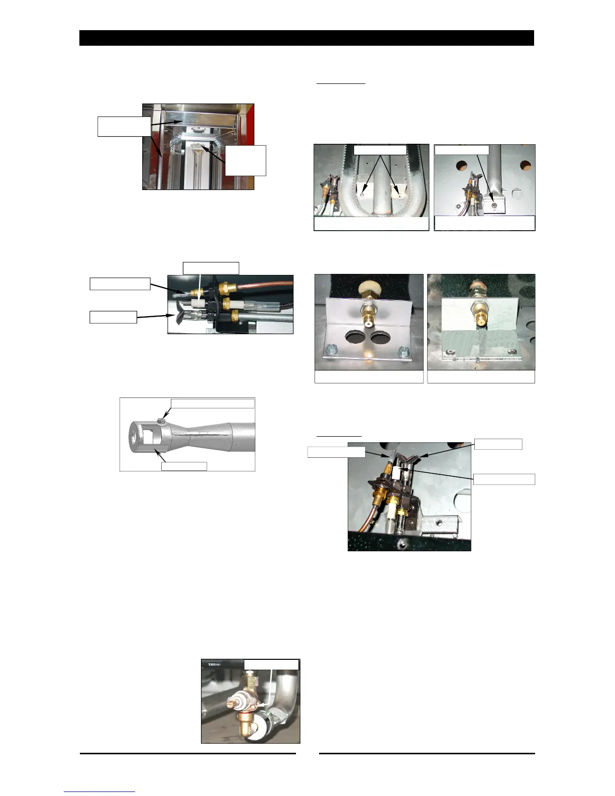
Low Fire Screw
Piezo Igniter
Thermocouple
Pilot Burner
Gas Control
Heat Shield
Burner
Securing
Screw
Burner Adjustment Screw
Aeration Slide
Oven
Main Burner
1. Turn off gas supply at main supply.
2. Remove oven racks, oven tray and flame baffle
from inside oven.
3. Remove the oven main burner.
4. Remove main burner injector and replace with
correct size injector. (Refer to ‘Gas
Specifications’ table at rear of this section).
5. Refit the following:-
Main burner.
Pilot Burner
1. Remove the following:-
Thermocouple (for access).
Piezo electrode (for access).
Unscrew pilot supply tube.
2. Remove pilot injector and replace with correct
size injector. (Refer to ‘Gas Specifications’ table
at rear of this section).
3. Refit the following:-
Thermocouple (removed for access).
Piezo electrode (removed for access).
Pilot supply tube.
Flame baffle.
Oven racks.
Oven trays.
Securing Screws
Securing Screw
Main Burner - CR6 Model
Main Burner - CR9 Model
Main Burner Injector - CR6 Main Burner Injector CR9
Thermocouple
Pilot Burner
Piezo Electrode
 Loading...