15
Part 6 Gas Conversion
Gas Conversion Procedure
NOTE:
These conversions should only be carried out by
qualified persons. All connections must be
checked for leaks before re-commissioning the
appliance.
Adjustment of components that have
adjustments / settings sealed (e.g. paint sealed)
can only be adjusted in accordance with the
following instructions and shall be re-sealed
before re-commissioning this appliance.
For all relevant gas specifications refer to the
tables at the end of this section.
Open Burners
1. Remove pot stands,
burner caps, burner
bodies and pot stand
supports.
2. Remove injectors and replace with correct size
injectors as shown in ‘Gas Specifications Tables’
at end of this section.
3. Refit pot stand supports, pot stands, burner caps
and burner bodies.
4. Re-light main burners and check flame size on
simmer (LOW) position.
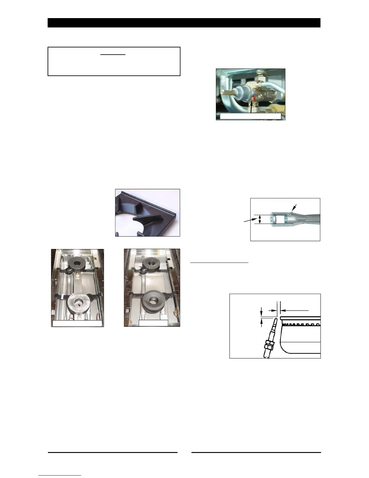
Low Fire Adjustment
Adjust low fire adjustment screw on open
burner gas control valves to obtain desired
flame size.
NOTE: The 'Low Fire Screw' should be sealed with
coloured paint on completion of low fire
adjustment.
Aeration Adjustment
1. Check / adjust main burner aeration gap. This
gap should be set to the dimensions shown in
the 'Gas Specification Tables' at the end of this
section.
Thermocouple Location
1. Check that thermocouple is correctly located
and that the gap between the thermocouple
and main burner is as shown in the diagram be-
low.
2. Check that the thermocouple to gas valve
connection is tight.
C
AUTION
:
Ensure that the unit is isolated from the gas
supply before commencing servicing.
Std Burners
Flame Failure Burners
Low Fire Adjustment Screw
Refer to 'Gas
Specification Tables'
Adjustment Screw
3 ±1 mm
2 ±1 mm
 Loading...