Do you have a question about the Cobra G100 and is the answer not in the manual?
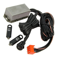
Main control unit of the system.
Set of cables for connecting system components.
Contains various small parts and accessories.
Transducers for detecting obstacles.
Siren with integrated backup battery.
Siren requiring external power.
Interface for system control and status indication.
Comprehensive guide for system setup and operation.
Card containing PIN code for system access.
Sticker for vehicle window warnings.
Remote control for system operation.
Specific wiring for the siren unit.
Guide for precise drilling during installation.
Mounting bracket for system components.
Card related to driver identification or system configuration.
Diagram for connecting without vehicle indicator lights flashing.
Diagram for connecting with vehicle indicator lights flashing.
Diagram for connecting the vehicle's original horn.
Diagram for connecting an optional supplementary siren.
Description of the central locking system module.
Unit providing comfort features like remote window control.
Sensor components for detecting presence or movement.
Module for immobilizing the engine.
Optional modules that extend system functionality.
Input for auxiliary modules or sensors.
Output for auxiliary devices or signals.
Wiring for LED indicator and transmitter/receiver modules.
Connections for dashboard and interior switches.
Wiring for door and trunk open/close sensors.
Wiring for an optional emergency panel.
Wiring for an optional internal buzzer.
| Starter Kill | Yes |
|---|---|
| Panic Mode | Yes |
| Alarm Type | 2-Way |
| Remote Control | Yes |
| LCD Display | Yes |
| Shock Sensor | Yes |