Page 4 of 12
Installation and Mounting:
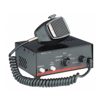
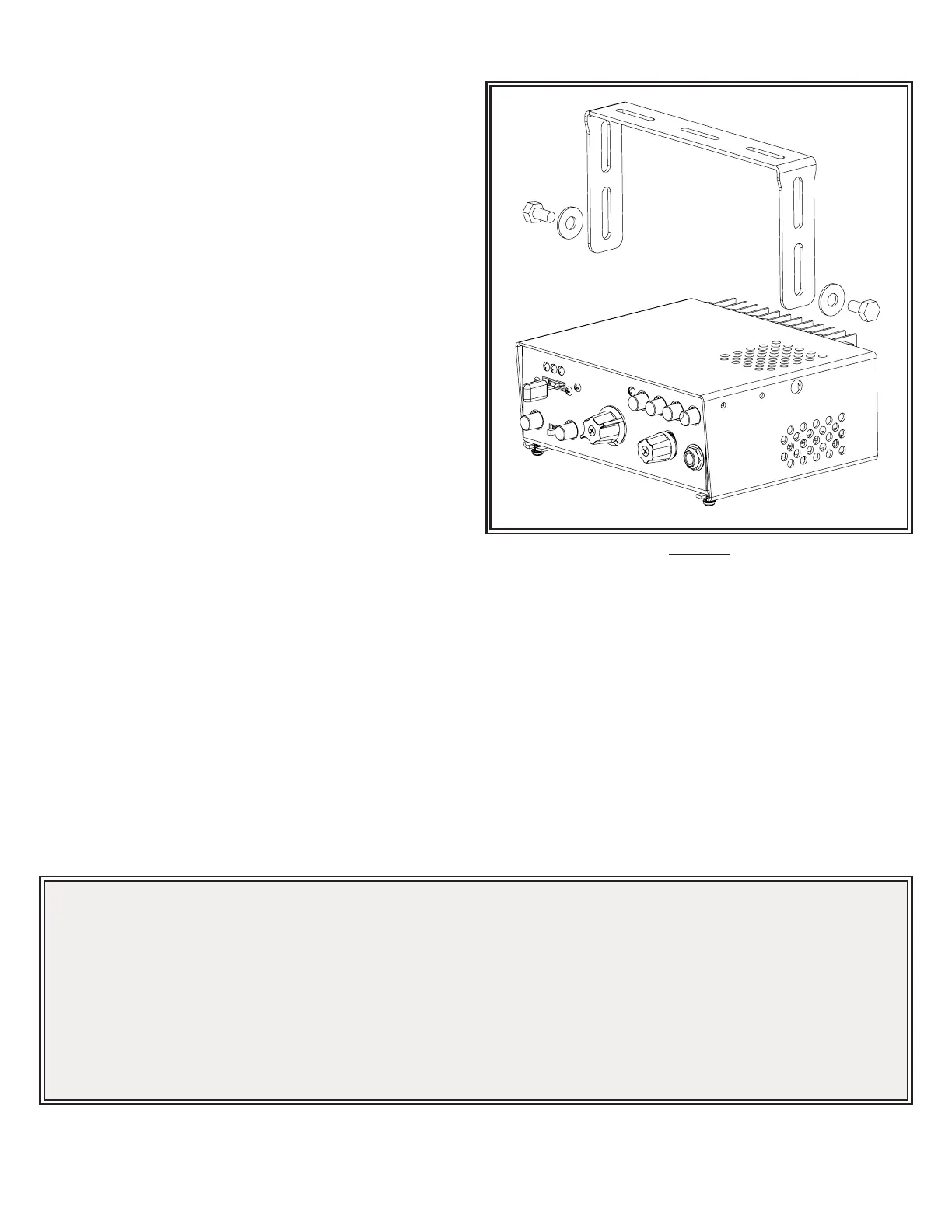
The siren may be mounted above the dash, below the dash, on a
tunnel or in a rack with the mounting bracket (bail) and the hardware
supplied (see Figure 2). Ease of operation and convenience to the
operator should be the prime consideration when mounting the siren
and controls.
Install the siren on the bail bracket using the 1/4-20 x 1/2” bolts and 1/4”
at washers supplied. Longer bolts will prevent removal of the chassis
from the cover and may damage internal components. See Figure 2 for
assembly and positioning details.
Note: Set-ups and adjustments will be made in subsequent steps,
depending upon the model and options purchased, that may
require access to the rear area of the unit. Plan the installation and
wiring accordingly.
Siren Amplier Connections:
As a standard feature, the Siren and Auxiliary sections (L4 models) of
your unit come equipped with a screw terminal block. To terminate the
wires, strip approximately 1/4” of insulation from the end of each wire
and insert it in the appropriate terminal. Tighten the screw and proceed
to the next connection.
8-Position Terminal Block Connections - (See Wiring Diagram)
S1 - +12VDC - connect to a positive +12 volt DC source. It is
recommended that the user protect this wire with a 20 Amp fuse or
circuit breaker located at the source. Use #14 gauge wire.
S2 - GROUND - connect to the negative terminal of the battery. This supplies ground (earth) to the siren. Use #14 gauge wire.
S3 - Speaker Common - connect to one of the wires from speaker.
S4 - 58W Speaker - connect to the remaining speaker lead for 58W speaker only.
S5 - 100/200W Speaker - connect to the remaining speaker lead for 100/200W operation (1-100W, 11 ohm speaker or 2-100W, 11 ohm
speakers connected in parallel).
S6 - Remote input (Horn Ring or foot switch) is factory set as a Tri-State input (accepts a positive (+12V) signal or a ground (earth)
signal). It can be recongured to accept a positive only signal or a ground only signal. See SET-UP AND ADJUSTMENT section for
details.
S7 - RRB - connect to one side of the two-way radio speaker.
S8 - RRB - connect to the second side of the two-way radio speaker.
Notes:
1. Larger wires and tight connections will provide longer service life for components. For high current wires it is highly recommended
that terminal blocks or soldered connections be used with shrink tubing to protect the connections. Do not use insulation displacement
connectors (e.g., 3M Scotchlock type connectors).
2. Route wiring using grommets and sealant when passing through compartment walls. Minimize the number of splices to reduce voltage
drop. All wiring should conform to the minimum wire size and other recommendations of the manufacturer and be protected from moving
parts and hot surfaces. Looms, grommets, cable ties, and similar installation hardware should be used to anchor and protect all wiring.
3. Fuses or circuit breakers should be located as close to the power takeo points as possible and properly sized to protect the wiring and
devices.
4. Particular attention should be paid to the location and method of making electrical connections and splices to protect these points from
corrosion and loss of conductivity.
5. Ground termination should only be made to substantial chassis components, preferably directly to the vehicle battery.
6. Circuit breakers are very sensitive to high temperatures and will “false trip” when mounted in hot environments or operated close to their
capacity.
Figure 2
 Loading...