Do you have a question about the Code 3 45 Series and is the answer not in the manual?
Essential safety instructions for installation and operation of emergency warning devices.
Details size and input voltage requirements for the LED Perimeter Light models.
Guidance on unpacking the light head and inspecting for transit damage.
Details three methods for attaching the LED base unit to the vehicle.
Guidance on routing wires, making connections, and ensuring proper wire slack.
Procedures for preparing the mounting surface, attaching the unit, and securing the lens.
Crucial guidelines for safe and effective electrical connections and wiring practices.
Details average current draw for various LED Perimeter Light models under different conditions.
Instructions on how to select and change flash patterns using the white wire.
Catalog of all available flash patterns with their corresponding number and description.
Exploded view and part numbers for the 45 series, including bezels and gaskets.
Exploded views and part numbers for 65 and 85 series lights by configuration.
Instructions for cleaning and replacing the light lens, with care warnings.
Diagrams illustrating the assembly of the LED light for headlamp housing.
Details the warranty period, exclusions, and limitations of liability.
Instructions on how to obtain an RGA number for product repair or replacement.
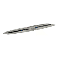
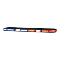
The document provides installation and operation instructions for the CODE 3 SERIES 45, 65, 85 LED PERIMETER STOP/TURN TAIL lights. These devices are designed as emergency warning lights for vehicles.
The LED Perimeter Lights serve as multi-functional warning devices, capable of steady burn, flashing patterns, and specific stop/turn/tail light functions depending on the model and wiring configuration. They are designed to enhance vehicle visibility for safety purposes, particularly in emergency situations. The lights are equipped with an exclusive feature of ten alternating flash patterns, and all patterns operate at either 75 or 150 flashes per minute (FPM).
Sizes and Dimensions:
Input Voltage:
LED Count and Current Draw (Average):
| Part Number | #of LEDs | Steady Burn 13.8VDC (Amps) | Flashing 13.8VDC (Amps) | Steady Burn 24.0VDC (Amps) | Flashing 24.0VDC (Amps) |
|---|---|---|---|---|---|
| 45, 45STA, 45STR - 7X3 PERIMETER | 62 | 1.0 | 0.5 | 0.5 | 0.3 |
| 65 - 6X4 PERIMETER | 76 | 1.0 | 0.5 | 0.5 | 0.3 |
| 85 - 9X7 PERIMETER | 124 | 1.5 | 0.8 | 0.8 | 0.4 |
| 65STR - 6X4 - RED (STOP OR TURN CONFIG.) | 54 | 0.7 | 0.4 | 0.4 | 0.2 |
| 65STR - 6X4 - RED (TAIL CONFIG.) | 54 | 0.05 | N/A | 0.04 | N/A |
| 65STA - 6X4 - AMBER TURN | 54 | 0.7 | 0.4 | 0.4 | 0.2 |
Wiring Functions:
Mounting Options: The LED base unit offers three mounting options:
Options 1 and 2 allow for removal of the outer lens without detaching the base from the vehicle, while option 3 allows for removal of the entire unit.
Installation Process: The installation involves determining the mounting location, verifying clearance, cutting a center opening for wiring, routing power wires, placing gaskets, preparing electrical connections, verifying cable length, testing light head operation, seating the O-ring, pushing connectors through the opening, pushing the LED base unit into the gasket, mounting the unit with screws or tape, and installing the lens. Specific instructions are provided for different screw types and tape application.
Flash Pattern Selection: The LED Perimeter Lights feature one steady burn and twenty flashing patterns, including ten alternating patterns. To select a pattern, apply +12 or +24 VDC to the red wire and connect the black wire to ground. The unit will flash in its last-set pattern. Momentarily touching the white wire to ground will cycle through the patterns. The unit retains the selected pattern even after power removal. For units flashed with an external control system (e.g., multiplexer or flasher), the heads should be set to steady burn. Permanently tying the white wire to the black wire forces a steady burn. It is recommended to set the desired pattern at a workbench before installation.
Safety Warnings: The manual emphasizes several critical safety warnings:
Lens Maintenance: The lens is field-removable for cleaning or replacement by unscrewing four mounting screws. It should be cleaned with mild detergent, warm water, and a soft cloth. Avoid using other chemicals, which may void the product warranty. The lens must be thoroughly dried before reinstallation. Because plastic scratches easily, cleaning is only recommended when necessary. Pressure washers and car washes with brushes should not be used as they can scratch the lenses.
Warranty: The manufacturer provides a Limited Warranty Policy for sixty (60) months from the date of purchase, ensuring the product conforms to specifications. The warranty is voided by tampering, accident, abuse, misuse, negligence, unapproved modifications, fire, improper installation/operation, or lack of maintenance. The manufacturer disclaims all other warranties, express or implied, including merchantability and fitness for a particular purpose. The sole liability and exclusive remedy for any non-conforming product is replacement, repair, or refund of the purchase price, not exceeding the original purchase amount. The manufacturer is not liable for lost profits, cost of substitute equipment/labor, property damage, or other special, consequential, or incidental damages.
Product Returns: For repair or replacement, customers must contact the factory to obtain a Return Goods Authorization Number (RGA number) before shipping the product. The RGA number should be clearly written on the package, and sufficient packing materials must be used to prevent transit damage. Code 3, Inc. reserves the right to repair or replace at its discretion and assumes no responsibility for removal/reinstallation expenses, packaging, handling, or shipping costs.
| Brand | Code 3 |
|---|---|
| Model | 45 Series |
| Category | Automobile Accessories |
| Language | English |