This document provides installation and operation instructions for the Code 3 V-CON Siren, a crucial component of an effective audio/visual emergency warning system. It emphasizes the importance of proper installation, operator training, and daily checks to ensure the safety of emergency personnel and the public.
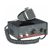
The V-CON Siren is designed to produce high sound levels for emergency signaling. It features a full-feature siren with various tones, a hardwire microphone, and an air horn. Specific models, such as the 3672L4S and 3692L4S, also include light controls, indicating a comprehensive warning system integration. The siren incorporates an Automatic Short Circuit Protection feature, which senses a short circuit on the speaker terminals and automatically puts the siren into standby mode until the fault is cleared, at which point it returns to normal operation.
A key operational feature is the Hit-n-Go Mode, which can be enabled by setting an internal slide switch on the V-CON amplifier board. This mode provides a seven-second override for all siren tones when activated by the Manual button or the Remote input, a familiar function for existing V-CON users. The siren offers industry-standard Wail, Yelp, and Hi-Lo tones, along with an electronic AIR HORN sound.
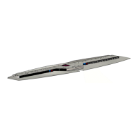
For communication, the device includes a Public Address (PA) function that overrides all siren functions when the microphone's Push-to-Talk (PTT) key is pressed. This allows for clear voice communication over the siren speakers. Additionally, a Radio Rebroadcast (RRB) feature enables the broadcast of two-way radio reception over the siren speakers. These inputs are transformer-coupled to prevent loading of the radio, ensuring optimal performance. The microphone itself is a noise-canceling, wired unit that can be easily unplugged internally for service or replacement.
The siren's front panel includes an Auxiliary Switch with a Status LED, which indicates the status of the A, B, C, and D Auxiliary switches (LED on signifies a switch is active). Remote Siren Switching is another versatile feature, allowing the siren to be connected to the vehicle's horn switch or another user-supplied switch to remotely activate either the MANUAL or AIR HORN function. The selection between these functions is made via a front panel slide switch. The siren is factory-set as a Tri-State input, accepting both positive (+12V) and ground (earth) signals, but can be reconfigured to accept positive-only or ground-only signals as needed.
The Tone Priority/Manual Wail feature allows for specific tones to be produced when the MANUAL Push-button is pressed or the user-supplied REMOTE siren switch is triggered. A Manual Wail is produced when the MANUAL Push-button is depressed while the rotary switch is in the STANDBY position. If the rotary switch is in the WAIL, YELP, HYPERYELP, or HI-LO position, pressing the MANUAL Push-button will produce a Yelp tone.
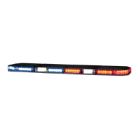
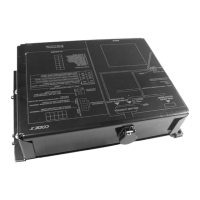
For L4 models, a Power Distribution Section is included, featuring a three-level progressive switch for primary warning light system control and four auxiliary switches. A #8 stud on the rear of the unit serves as a convenient ground "tie-point" for light bar wiring, though it is specified not to be an adequate ground for the siren or the light bar itself.
Installation involves mounting the siren above or below the dash, on a tunnel, or in a rack using the provided mounting bracket and hardware. Ease of operation and operator convenience are primary considerations for mounting the siren and its controls. Wiring connections are made via an 8-position screw terminal block for the siren amplifier and an 11-position terminal block for lighting control in L4 models. Important notes on wiring emphasize using larger wires, tight connections, grommets, sealant, and proper fusing to ensure longevity, protect against damage, and maintain conductivity.
Set-up and adjustment procedures are crucial before final mounting. Audio adjustments include the PA/RRB Volume Adjustment, located on the front panel, which sets the PA and RRB volume to prevent feedback and ensure intelligible audio. The Radio Re-broadcast Adjustment involves adjusting a MAX RRB trimmer on the rear panel to set the maximum RRB level, ensuring the desired volume is produced outside the vehicle by the siren speaker.
Remote Input Adjustments allow the remote input to be configured in one of three modes: Tri-State Input (accepts positive or ground signal), Positive Only Input (accepts only positive signal), or Ground Only Input (accepts only ground signal). The configuration process involves powering up the siren while pressing specific buttons (MANUAL or AIR HORN) for approximately three seconds.
Configuration Switch Adjustments, accessible via internal slide switches, include Hit & Go, LightAlert, and SirenLock. The Hit & Go switch enables or defeats the Hit-n-Go feature. The SirenLock option, when active, restricts siren tones (Wail, Yelp, Hi-Lo) to be produced only when the 3-Level Warning Light Switch is in the Lighting Level 2 or Level 3 positions, a feature often required by jurisdictions that mandate warning lights to be on before the siren is activated. Air Horn, Radio Rebroadcast, and Public Address functions are unaffected by SirenLock. The SirenLock can be configured to operate in Level 3 only or in both Levels 2 and 3 using a level select switch.
Operation of the Rotary Function Selector Switch dictates the siren's mode:
- RADIO: Audio from the 2-way radio is rebroadcast; siren tones are inactive.
- STANDBY: Manual wail ramps up and down when the MANUAL button is pressed and released. AIR HORN button produces the Air Horn sound.
- WAIL: Produces the Wail tone. MANUAL button produces Yelp for 7 seconds. AIR HORN button produces Air Horn, then returns to Wail.
- YELP: Produces the Yelp tone. MANUAL button continues Yelp. AIR HORN button produces Air Horn, then returns to Yelp.
- HI-LO: Produces the Hi-Lo tone. MANUAL button produces Yelp for 7 seconds. AIR HORN button produces Air Horn, then returns to Hi-Lo.
The P.A. VOLUME Knob adjusts the PA audio level and the Radio Re-broadcast level. The Push-to-Talk (PTT) Microphone Switch overrides any siren mode for public address messages. The MANUAL Push-button Momentary Switch and AIR HORN Push-button Momentary Switch (for models 3692 and 3692L4) activate specific tones as described for each selector position. A Slide Switch (for models 3692 and 3692L4) located between the AIR HORN and MANUAL buttons selects the function for the REMOTE circuitry, allowing it to remotely "depress" either the AIR HORN button or the MANUAL pushbutton.
Lighting Controls (for L4 Models Only) include Auxiliary Switches A, B, C, and D, which supply power to connected loads. Auxiliary Switch C operates a SPDT circuit that can be momentary or latching. The Warning Light 3-Level Progressive Slide Switch controls three levels of warning lights, progressively activating Green, Yellow, and Red LEDs and enabling LightAlert and SirenLock options as supplied.
Optional features include SirenLock™ (L4 and L6 Models Only), an interlock circuit that permits automatic siren tones only when the progressive switch is in Level 3 or in Level 2 or 3, depending on user selection. This feature is crucial for jurisdictions requiring warning lights to be on before siren activation. InterClear® is a unique feature that activates additional warning lights for 7 seconds during Hit-N-Go override or "scrolling" by pushing a button or horn ring, providing an extra layer of warning in critical situations like intersections. A Pluggable Microphone option allows for a plug-in noise-canceling microphone instead of the standard wired-in unit.
Maintenance involves troubleshooting common issues such as no siren output, external fuse blows, low volume, speaker failure, and power distribution problems. The manual provides probable causes and remedies, including checking connections, polarity, speaker wiring, vehicle charging system, microphone integrity, and fuse status. It also advises on using correct speaker types and ensuring proper grounding.
The manufacturer provides a Limited Warranty Policy, covering the product for sixty (60) months from the purchase date, provided it is installed and used according to manufacturer recommendations. The warranty is voided by tampering, accident, abuse, misuse, negligence, unapproved modifications, fire, improper installation or operation, or lack of maintenance. The manufacturer disclaims all other warranties, express or implied, and limits its liability to replacement, repair, or refund of the purchase price. Product returns require a Return Goods Authorization Number (RGA) from the factory.