920-0655-00 Rev B
Page 3 of 8
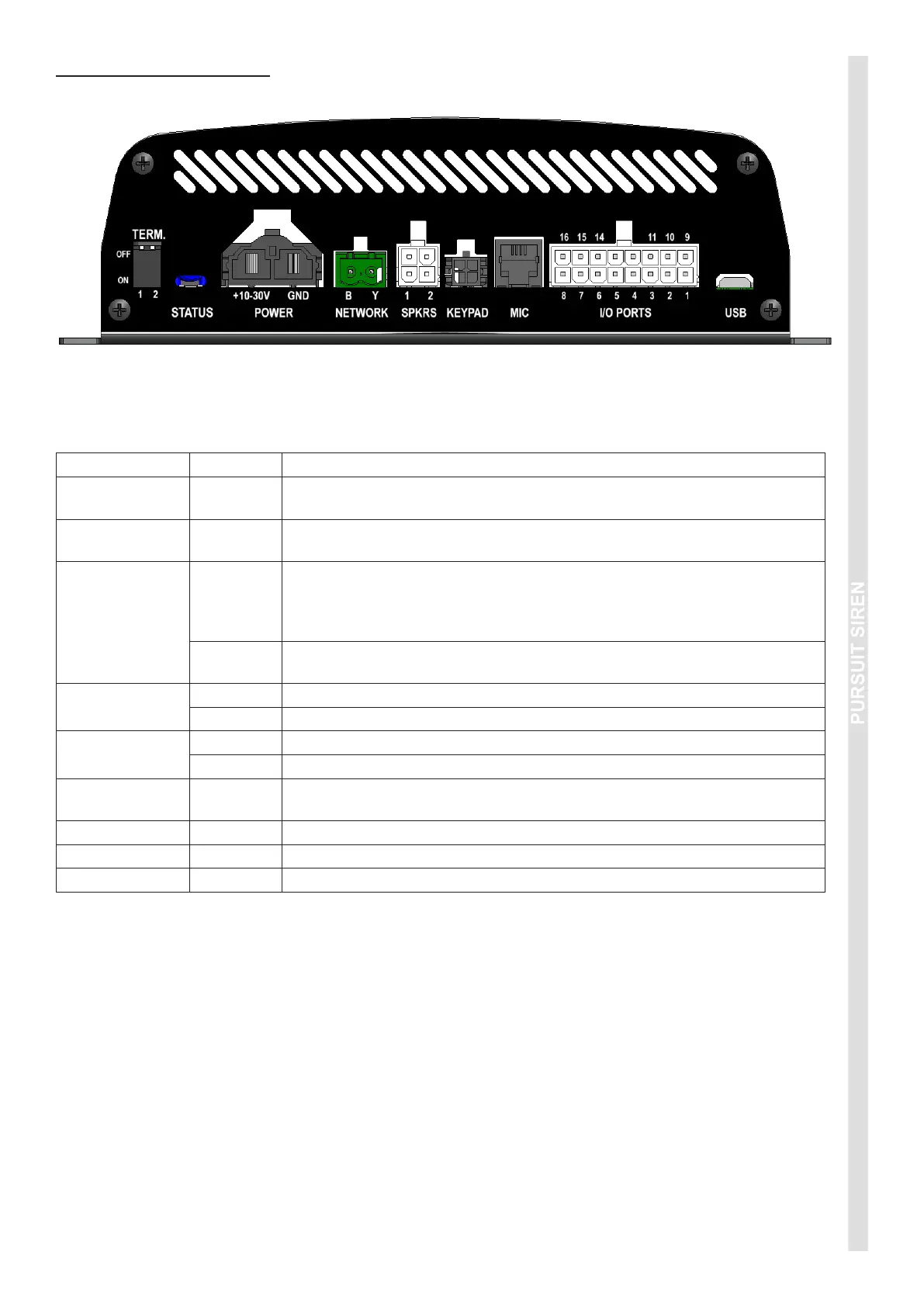
WIRING INSTRUCTIONS
Before proceeding with installation, plan all cable routing and wiring carefully.
PORT REF DESCRIPTION
TERM.
Network termination setting. Default 1=ON; 2=OFF. For further details, refer
to Network Application Note.
STATUS
The Status LEDs indicate various aspects of the current operation of the
siren. RED = Bootloader (programming mode / rmware update).
POWER
+10-30V
Connect to 4.5mm² (10 AWG) automotive wire to a fused power source,
using the shortest possible wire length. Fuses should be 15A for 100W
variants, and 25A for 200W variants. Do not connect this power wire until
all other connections have been made to the unit.
GND
Connect to 4.5mm² (10 AWG) automotive wire to a good chassis ground
point or the battery negative terminal, using the shortest possible wire length.
NETWORK
B Connect the Blue wire from the HazCAN device(s).*
Y Connect the Yellow wire from the HazCAN device(s).*
SPKRS
1 Connect Speaker 1 here.
2 Connect Speaker 2 here (for 200W applications only).
KEYPAD
Connect HazCAN compatible devices (via extension cable if required) to this
port (optional).
MIC Connect the microphone here.
I/O PORTS Refer wiring diagram.
USB Conguration and rmware updates via Software Graphical User Interface.
*Network cable requirements: Twisted pair, 30mm pitch Blue/Yellow. 0.25mm
2
/ 24AWG.