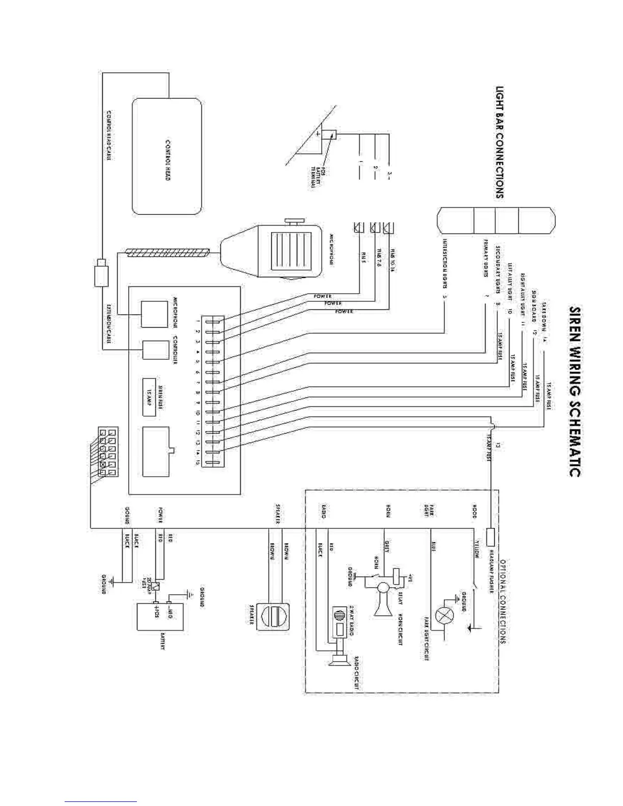
Figure 1 - Wiring Diagram
10 AMP
20 AMP FUSE
20 AMP FUSE
20 AMP FUSE
3. To install the positive and negative power wires, strip 1/4” of insulation from the end of the wires, and install the blade
connectors onto the ends of the appropriate wires. The “+24V” positions may be connected either directly to a +24V
source (such as a battery), or through a switch (such as an ignition switch). (See proper fusing requirements on page
6 prior to making any wire connections to battery or ignition switch)
T56095 Rev. A Page 5 of 22