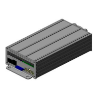
4. The unit is supplied with a twelve-position, pluggable connector (white color) for connections to the speaker and other
selected optional connections such as hood,grill, radio, horn ring and parklight . Main light bar connections are made
at the blade connections in the back of the amplier unit and are labelled with identication to coincide with the control
head.
5. Speaker – the siren is designed to operate with one 11-ohm impedance speaker (100W). Speakers are not included as
part of the siren. Any 11-ohm 100W speaker for use with emergency vehicle may be considered to use.
6. To install the light bar power wires, strip approximately 1/4″ of insulation from the end of the lights wires. Install the blade
wire connectors onto the wire ends and connect the appropriate wires to the terminals on the amplier housing to co-
incide with the light bar wire function identication. Keep in mind that terminals 8, and 10-14 have a 15 amp maximum
current each. Power wires on pins 1,2 and 3 have a max. current of 15A each.
External 20A fuse is required on each of the 3 individual +24V power wires on pins 1,2 and 3 at the battery feed.
(Pin 4 is not used)
Pin 5 max current of 15A.
Pin 7 max current 15A.
Pin 8 internally fused for 15A
(Pin 9 not used)
Pins 10 - 14 are all internally fused for 15A each. (See gure 5, page 9 for fuse location)
- left alley ( Pin 10),
- right alley ( Pin 11),
- sign light ( Pin 12),
- headlight asher ( Pin 13),
- take down lights ( Pin 14).
(Pin 15 not used)
7. If a fuse is installed, it should be sized for the actual load of the lighting used and located as close to the battery positive
as possible.
8. Ensure that there are no loose wire strands or other bare wire that may cause a short circuit. All wires must be protected
from any sharp edged that could eventually cut through the insulation. Also use an ohmmeter to verify that a short circuit
does not exist between the positive (+) leads and the vehicles chassis.
CONNECTION OF A 58 WATT SPEAKER TO THE SPKR TERMINAL WILL CAUSE THE SPEAKER
TO BURN OUT, AND WILL VOID THE SPEAKER WARRANTY!
Any electronic device my create or be affected by electromagnetic interference. After installation
of any electronic device, operate all equipment simultaneously to insure that operation is free of
interference.
T56095 Rev. A Page 6 of 22