9
Wiring Instructions
Larger wires and tight connections will provide longer service life for components. For high current wires it is
highly recommended that terminal blocks or soldered connections be used with shrink tubing to protect the
connections. Do not use insulation displacement connectors (e.g. 3M
®
Scotchlock type connectors). Route
wiring using grommets and sealant when passing through compartment walls. Minimize the number of splices to
reduce voltage drop. High ambient temperatures (e.g. underhood) will significantly reduce the current carrying
capacity of wires, fuses, and circuit breakers. Use "SXL" type wire in engine compartment. All wiring should
conform to the minimum wire size and other recommendations of the manufacturer and be protected from moving
parts and hot surfaces. Looms, grommets, cable ties, and similar installation hardware should be used to
anchor and protect all wiring. Fuses or circuit breakers should be located as close to the power takeoff points as
possible and properly sized to protect the wiring and devices. Particular attention should be paid to the location
and method of making electrical connections and splices to protect these points from corrosion and loss of
conductivity. Ground terminations should only be made to substantial chassis components, preferably directly to
the vehicle battery. The user should install a fuse sized to approximately 125% of the maximum Amp capacity in
the supply line to protect against short circuits. For example, a 30 Amp fuse should carry a maximum of 24
Amps. DO NOT USE 1/4" DIAMETER GLASS FUSES AS THEY ARE NOT SUITABLE FOR CONTINUOUS
DUTY IN SIZES ABOVE 15 AMPS. Circuit breakers are very sensitive to high temperatures and will "false trip"
when mounted in hot environments or operated close to their capacity.
WARNING!
!
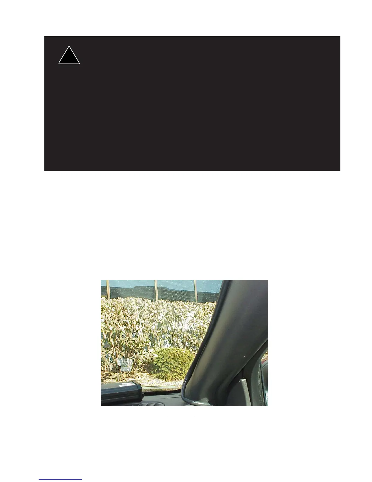
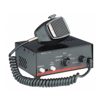
Route the wiring cable into the passenger compartment as shown in Figure 12. It is advisable to leave an extra loop of cable
when installing the light bar to allow for future changes or reinstallations. Connect the black lead to a solid frame ground
(earth), preferably, the (-) or ground (earth) side of the battery, and the remaining power wires to the +12V terminal of the
battery, power switches, siren or RLS controller. The MR8 takedowns may be installed to a flasher. The fan should be wired to
operate continuously whenever the takedowns are in operation, either flashing or steady burn. Each light head is wired
independently to allow complete flexibility of control.
FIGURE 12