11
Troubleshooting
All SuperVisors are thoroughly tested prior to shipment. However, should you encounter a problem during installation or during the
life of the product, follow the guide below for information on repair and troubleshooting. Additional information may be obtained from
the factory technical help line at 314-996-2800.
Follow the guide below for information on repair and troubleshooting.
TROUBLESHOOTING GUIDE
Note: LED modules must be replaced as a module. There are no user serviceable parts.
PROBLEM
LED module not
operating when
powered.
QUESTIONS POSSIBLE CAUSE
a. Bad power/ground
connection.
b. Defective module.
SOLUTION
a. Fix connection.
b. Replace module
N/A
Directional module Flash Pattern - Table 2
Flash Pattern Description
Cycle Flash Cycles through various patterns @ 70 fpm
Steady-Burn Steady-Burn
Five Flash Five Pulses per flash @ 70 fpm
Quad Flash Four Pulses per flash @ 70 fpm
Triple Flash Three Pulses per flash @ 70 fpm
Double Flash Two Pulses per flash @ 70 fpm
Fast Double Flash Two Pulses per flash @ 85 fpm
NFPA Four Pulses, 70% Duty Cycle @ 75 fpm
Quad Pop Flash Four Pulses per flash ( 3 equal, 1 extended) @ 70 fpm
Triple Pop Flash Three Pulses per flash ( 2 equal, 1 extended) @ 70 fpm
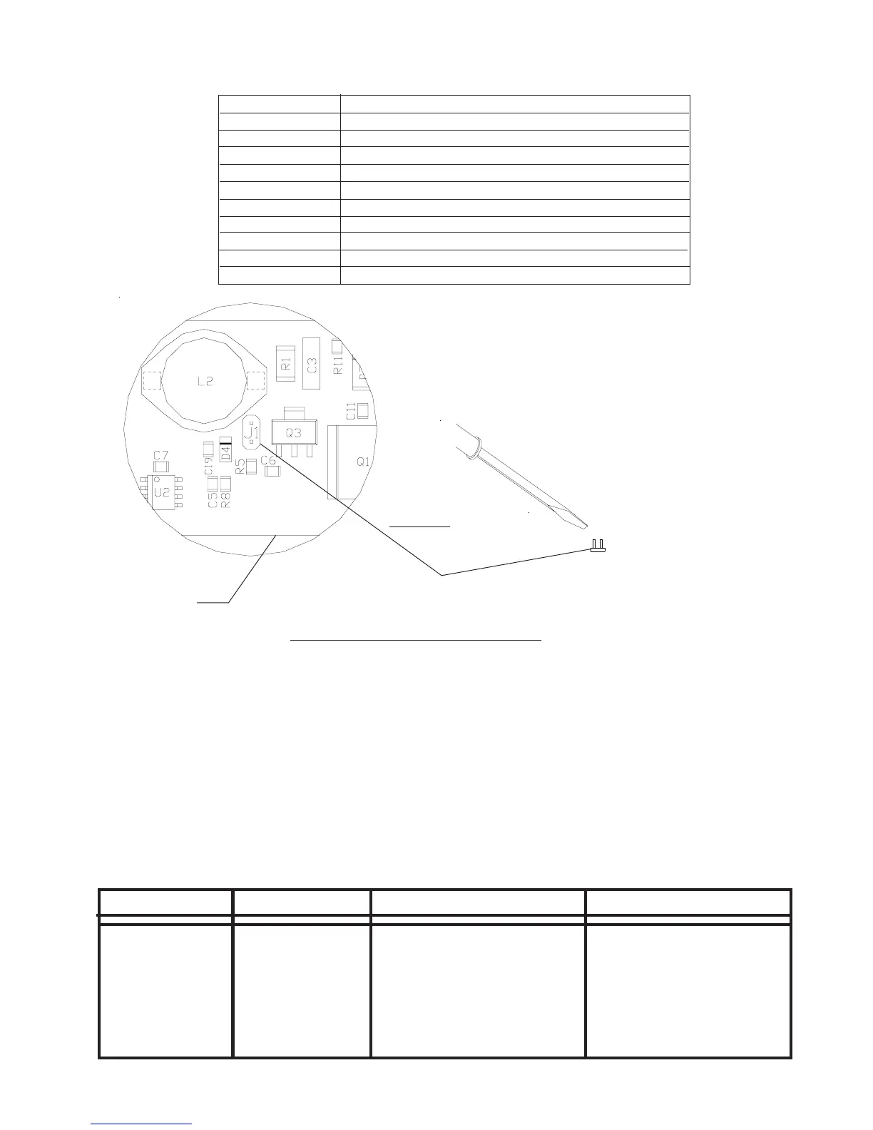
FIGURE 33
Flash Pattern Header for OPTIX/LEDX
J1
PCB
Momentarily short and release
to change patterns