ca1155 Quick Ref. rev C
Adjusting the Shock Sensor
1. Increase sensitivity by turning the adjustment dial clockwise.
2. Decrease sensitivity by turning the adjustment dial counter clockwise.
Testing the Shock Sensor
Arm the system and wait 6 seconds for the zone to stabilize, then rmly strike the
vehicles bumper.
PROFESSIONAL
SERIES
Security and Keyless Entry
Installation Quick Reference
Guide
for model:
ca1155
SHOCK SENSOR PORT
PROGRAMMING / VALET PORT
LED PORT
DBI PORT
CA 1155
# 4360712
BROWN SIREN OUTPUT ( + )
RED BATTERY 12V ( + )
BLACK GROUND
BROWN/BLACK UNLOCK SWITCH ( 87A )
VIOLET/BLACK UNLOCK POLARITY ( 87 )
VIOLET LOCK POLARITY ( 87 )
GREEN/BLACK LOCK MOTOR ( 30 )
WHITE PARKING LIGHT OUTPUT
WHITE/RED PARKING LIGHT INPUT
WHITE PARKING LIGHT OUTPUT
WHITE/BLACK LOCK SWITCH ( 87A )
BLUE/BLACK UNLOCK MOTOR ( 30 )
# 4120402
PURPLE DOOR TRIGGER INPUT ( + )
GREEN/BLACK FACTORY DISARM OUTPUT ( - )
OPEN
GREEN DOOR TRIGGER INPUT ( - )
ORANGE ARMED OUTPUT ( - )
BROWN/BLACK HORN OUTPUT ( - )
VIOLET/BLACK AUX 1 OUTPUT ( - )
GRAY HOOD PIN INPUT ( - )
YELLOW IGNITION INPUT ( + )
RED/WHITE TRUNK RELEASE OUTPUT ( - )
# 4120403
# 1024363
# 1024389
RED
BATTERY 12V ( + )
BLACK
GROUND WHEN
BLUE FULL TRIGGER ( - )
GREEN WARN AWAY TRIGGER ( - )
SHOCK SENSOR & HARNESS
#4700023
86
85
30
87
87a
Programming Note:
P
The default wire function settings are listed next
to the wire color. Wires shown with can be
programmed to perform different functions.
Refer to the Feature Programming section to
change the default setting.
P
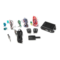
Replacement Part
Power / Notification
Harness
(12-Pin)
Input / Output
Harness
(10-Pin)
Valet Harness
(2-Pin)
Replacement Part
LED
(2-Pin)
Replacement Part
Replacement Part
Replacement Part
ORANGE 86 - ARMED OUTPUT ( - )
RED 85 - IGNITION ( + )
BLACK 87A - STARTER OUTPUT - MOTOR SIDE
WHITE / BLACK 30 - STARTER INPUT - KEY SIDE
STARTER INTERUPT RELAY & HARNESS
#1024405
Replacement Part
Replacement Part
P
P
P
P
P
P
P
P
Security Trigger Zones
If the security system has been triggered the LED will ash one of the patterns below
indicating the zone.
LED FLASHES TRIGGER ZONE
2 Flashes Hood / Trunk Input
3 Flashes Door Input
4 Flashes Shock Sensor
5 Flashes Ignition Input
2020 Voxx Electronics Corporation. All rights reserved.
Complete guides also available at
www.voxxuniversity.com
**This guide is a reference for module rmware version 5.0 or higher**